Ball Joint Mysteries

Ball Joint Mysteries

Anonymous
Not applicable
9,914 Views
28 Replies
Message 1 of 29

Ball Joint Mysteries

Anonymous
Not applicable


I think I understand ball joint motions but I don't understand how to set them up, install them correctly, orient them or change them.


My goal is to animate the mannequin's arms (see below) to imitate the corresponding motions of the mechanical wings (second image) but I'm not making much headway.


I don't understand the dialog boxes, the animations or the joint-flags. For instance, in the "edit joint limits" dialog box, both the Pitch and Roll animations seem to show exactly the same motions, i.e., rotation about the long axis of the arm. I can't get  simple sweeps of an arm without some twisting action being thrown in and sometimes some bending at the elbow and/or wrist. There are strange jumps when joint limits are exceeded and sometimes an arm snaps back to its starting position (or some new position) and sometimes not.


I've had some success by creating a rigid group between the mannequin's left hand and the haptic interface handgrip (third image) but the motion is severely limited and temporarily crashes the program when limits are exceeded.


Clearly, I need some help. Are there any Screencasts or other instructions out there that might explain how all of this works?


I've attached the mannequin's .f3d file.


Ball Joint Mysteries.png 


View From Below.png


 Haptic Interface.png

 
0 Likes
Accepted solutions (1)
9,915 Views
28 Replies
Replies (28)
Message 2 of 29

innovatenate
Autodesk Support
Autodesk Support

There's an AU class below that may be helpful to reference.


http://au.autodesk.com/au-online/classes-on-demand/class-catalog/2015/fusion-360/cp10165#chapter=0


Each ball joint has 3 axis of rotation. I believe in this case, due to the current angle offset, it appears that there are only two axis of rotation. See the below screencast for clarification.


I hope that helps. Let us know if you have any other quesitons!
 
Thanks,


Nathan Chandler
Principal Specialist
Message 3 of 29

jeff_strater
Community Manager
Community Manager

Hi @Anonymous,


You are not alone here.  Ball joints can be finicky.  Part of the problem is that Ball joint math in Fusion is implemented using an Euler formulation that is subject to Gimbal Lock.  This is what you see when more than one axis is aligned.  We had an internal discussion a long time ago about changing that math, but the other way to implement these has problems of its own.  I don't pretend to understand the math.  But, we use the "ZXZ" formulation for ball joints, which is subject to Gimbal Lock.  We discussed using the "ZYX" formulation, but it has other problems, so we never did that.


Regarding the behavior, do you see this on simple component drag, Drive Joint, Animate Joint, Animate Model, or all of these?  I had pretty good luck with your model using Drive Joint, but the behavior you describe does not surprise me.  If you can take the time to record a screencast of what you are seeing, we might be able to offer some help.


One thing you can try:  There is a text command called "Joints.SmoothBallJointDrag /on", that is supposed to make ball joint solving better.  But, I don't understand what this really does internally.  I think it's safe to try, though.


And, your solution of adding more joints to the hands, to help corral the "side effects" of other joints moving unexpectedly is also a good one.  The problem is that this system is highly underconstrained.  So, when the shoulder joint moves, it can sometimes make other joints move, because that is a valid solution to the constraint system.


Noe of this really helps you, sorry to say, but hopefully sheds some light on the subject.


Jeff


Jeff Strater
Engineering Director
Message 4 of 29

Anonymous
Not applicable

You should have used Quaternions.


"But, but it has other problems!"


Of course, but they don't matter, ball joint, should use Quaternions, always, Euler is REALLY, REALLY, REALLY bad idea.


There is no reason whatsoever to have used Euler there.


Whoever made the decision to keep it as Euler, should be demoted, I don't know a single programmer (I am a programmer myself) that doesn't know this, even if they have no idea how to do the math (I personally don't either), but it is widely common knowledge, that you should use Quaternions or some other kind of 4D math, any 3D math method will have problems with gimbal lock, and that is a big no no, it is common sense as it is in the cooking industry that you should put salt on the foot.

0 Likes
Message 5 of 29

kgrunawalt
Autodesk
Autodesk

Hi,


Our ball joints are gimbals in a ZX'Z" configuration. This provides three relatively intuitive rotation angles (unlike quaternions which would be very ugly to expose as parameters). However, this bears some explanation that the UI does not currently give. hence some confusion. I'll try to clarify. BTW, this is not different from other systems used very widely for precise ball motion (maya, etc.). Maya exposes more Euler variations than ZXZ. If that is worth doing in Fusion, we could do that.
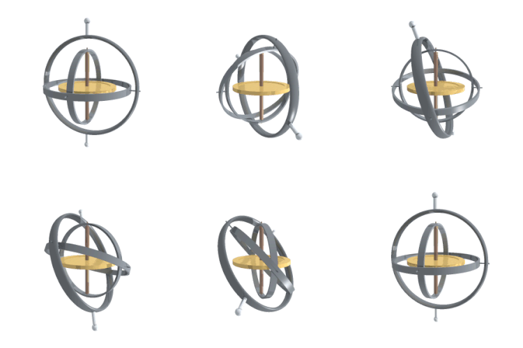
 

A gimbal ball joint is essentially a set of three revolute joints in a series, with two virtual gimbal bodies between the first side and second side of the joint:


     First component + revZ + (gimbal1) + revX + (gimbal2) + revZ + Second component


The ZX'Z" arrangement is a classic Euler relative arrangment. Each revolute rotates about an axis defined by the joint geometry selections. For example, if you put a ball joint using spherical geometry and a spherical cut, the default ball joint angles will:

  1. Rotate about the aligned Z axes of the first component and (gimbal1)
  2. Rotate about aligned X axes of (gimbal1) and (gimbal2)
  3. Rotate about the aligned Z axes of (gimbal2) and second component


The Z axes default to the Z axes of the selected components, but certain geometry selections will override this to define the axis. For example, a circular edge defines a z axis as the circle axis. Spherical surfaces do not define an axis, so ball joints typically use the selected component's origin z axes. This can be overridden with the joint options during creation and edit.


It might seem odd to have ZX'Z" instead of XY'Z" (which is a Tait Bryan Euler arrangement), but there is a reason for this common choice. A ball joint using ZXZ (or ZYZ, etc) has some nice intuitive motion properties:


  • Limits on X' define a cone of freedom about the Z which is often desired -- like an actual ball in a conical socket
  • Z" motion provides a nice roll about the axis of the joystick (if you think of the stick as the joint z axis on the second component. If you don't want this roll, you can lock it.

The one negative of ZX'Z" is that initially the outer Z angles have aligned axes when the X' angle is zero. This is called gimbal lock, but this is not as bad as it sounds. It just means that the X' needs to rotate to unalign Z from Z". This happens automatically with dragging (with the smooth dragging mode mentioned by Jeff as the Fusion default BTW). There is no real loss of motion. You just need to drive X' angle to be the desired angle for rotating about Z"


The XY'Z" arrangement is not initially in gimbal lock, but it still can be in lock after a rotation. However, the XYZ arrangment does not have the two nice properties mentioned above.


Parameters


All Fusion joints are fully parametic. Each degree of freedom (angle or distance) is a parameter that is exposed in the context of a "Position" feature when the user drives a joint value and in the context of a new or edited "Position" feature. These Position feature parameter can be set to an equation.


It is therefore important that these parameters have physical meaning that is not too obscure. For most joints, the choice is obvious. A revolute joint has an angle. A cylindrical joint has an angle and a distance. For a ball joint, the parameter choice is more complex. For the reasons I mention above, we found the ZX'Z" angle provide useful meaning for many uses.


We could offer more ball joint angle configurations that supply different parametric meanings (XYZ, etc.) This is something we have discussed, but we didn't want to add unwanted complexity.


We could even supply quaternion parameters if desired (four values) -- although these are not very intuitive. They do provide four independent variables with no gimbal lock. This is why they are attractive for some applications. They are not so great for key-ing in values to get precise orientations. We think the ZXZ euler gimbal lock issue is simply remedied (see above) and the benefits are worth it. This might not be the case for some people or some specific applications!


Summary


We put a lot of thought into our choice for ball joint parameters because no choice is perfect for all applications and any choice requires some explanation to make sense. We decided to accept the ZX'Z" gimbal lock with the green/X' angle is 0/180 degrees. It is easy to rotate this angle to make Z and Z" different axes and ZXZ has nice motion properties and fairly intuitive angle parameters.


However, we can expose other parameter arrangements. Some are less intuitive than others, but may be appropriate for certain applications.


Message 6 of 29

kgrunawalt
Autodesk
Autodesk

I'll add two suggestions for ball joint creation.


First, get the Z's right. The Z axes of the two components (or defined by selected geometries) might not be what you want. For example, if making a joystick, the red/blue arrows should rotate about the shaft of the joystick. Then the Z" angle will roll the stick and the Y' angle limit will define a nice cone of motion if desired.


You can use the joint options to redefine the Z's, either to choose an orthogonal axis to be defined by an additional selection (custom).


Second, if you are frustrated by the Z's being aligned (gimbal lock), unalign them by changing the X' angle to be other than 0 or 180 degrees. You can do this using the "drive joint" command. Dragging will probably result in rather arbitrary values for ZX'Z". You can lock the X' if you want, but then you'll have two angled spinning axes -- probably not what you want in a skeleton!


Message 7 of 29

TrippyLighting
Consultant
Consultant

Phenomenal explanation, really!

This should be a straight copy/paste into the documentation for Fusion 360.


EESignature

Message 8 of 29

TrippyLighting
Consultant
Consultant

@Anonymous wrote:


Whoever made the decision to keep it as Euler, should be demoted.


@Anonymous It is time, perhaps, to recognize that there are some behavioral ground rules on this forum and you'd be well avised to read those before you make more inflamatory and unconstructive remarks!


EESignature

Message 9 of 29

Anonymous
Not applicable


Thanks Nathan,


I watched the video of the class on joints and picked up a number of useful tidbits but what was really helpful was your Screencast here. Once I realized that you were doing a quick double-click on the ball-joint flags to bring up the manipulators, it started to make more sense (I was also confused by the "SHIFT" signs that kept popping up on-screen since you don't need to shift-click to bring them up). Anyway, getting to the manipulators helped a lot; I had never seen them before in relation to joint flags.


Now, the main problem is that I don't understand is how I can pick out a particular axis to make a motion link to. In order to get the mannequin to mimic the wing motions, I think I need to somehow make motion links to the corresponding joints in the wing. At least that's the plan for now.


I still don't understand all the stuff going on with the joint-symbols and motions but you've give me a good start. I'll probably be back to ask more questions when I can figure out more clearly what I don't understand.

Message 10 of 29

Anonymous
Not applicable


This is great. You and the other experts here have given me a load of really useful information about ball joints and thrown in a fascinating discussion about gimbals and gimbal lock to boot. So most of the mysteries surrounding ball joints have been resolved and I now have control over the individual pitch, yaw and roll axes. I can't believe I didn't know that a double-click brings up the manipulators (and I love the manipulators) but there it is. Anyway, thanks very much for all of this.


I'm still thoroughly confused, though, about the relationship between the ball joint axes and the component's origin axes. Your say that The Z axes default to the Z axes of the selected components but I don't know which components are being referred to (I'm not familiar with the ZX'Z" notation, either).


In the image below, the ball joint's long flag (the pitch flag) lines up parallel not to the arm origin's Z axis (which is visible) but parallel to the Z axis of the origin of the torso (which is not visible). It also rotates the arm about an axis (the dashed line) parallel to the X axis of the torso's origin. So, it's not clear what components are the "selected" ones you refer to above or how, really, any of this works. My apologies for being so confused.


Ultimately, I want to make a motion link between the arm and the wing's power stroke (rev10 in the actuator unit, which is angled 25 degrees forward of straight down). Any suggestions as to the best way to go about this would be greatly appreciated.


Axes Orientation 2.png


0 Likes
Message 11 of 29

Anonymous
Not applicable


"... do you see this on simple component drag, Drive Joint, Animate Joint, Animate Model, or all of these? ..."


Only on component drag. I'm just learning about Drive Joint but I can't recall any weirdness there. Animate Joint and Animate Model function well. I'm getting more familiar with all this (thanks very much) but I haven't had the nerve to try "Joints.SmoothBallJointDrag /on". I haven't forgotten about it, though.


It makes sense, given the long chains of joints involved, that strange things would happen if you drag components around at random and mix in some gimbal-locking. So I do need to figure out how to add more constraints to the system to corral the "side effects" as you say.


You've been quite helpful.


0 Likes
Message 12 of 29

kgrunawalt
Autodesk
Autodesk
Accepted solution

Hi,


The use of the X,Y,Z axes terms in relation to  joints is somewhat confusing. The UI could be improved to make this more clear. I'll try to clarify.


In an as-built joint, the joint itself is previewed when it is placed by selecting geometry. You can tell how a revolute will work before it is placed. Fusion will calculate the two joint origins in the two joined component spaces based on the selected geometry. In an assembling joint where you pick two geometries to align, Fusion displays a disc with half-moon cutout for each selection. This is the "joint origin" which is either defined implicitly during joint creation or explicitly beforehand using the Joint Origin command.


It could be that most of the difficultly you are having is due to lack of regular geometry that will define obvious coordinate systems when selected.


Joint origins are just user-defined coordinate systems in the space of the components being joined. For example, a circular edge defines an origin point and primary axis. The secondary axis needed to fully define a coordinate system is not inferred from the circle. Fusion will use the origin coordinate system of the component that owns the geometry to infer the secondary axis. The Joint Origin command provides options to customize this coordinate system definition. The Joint command provides options to customize the alignment of two joint origins to define the motion of the joint.


The joint origin primary axis (normal to the displayed disc glyph) is the local coordinate's z axis. This is an internal convention that unfortunately gets exposed in the alignment options of the joint command. It would be good to fix this somehow. Ideally, you should not think in terms of the x,y,z axes of joint origin coordinate systems!


So how does this help you?


The ball joint is essentially three revolute joints with two internal virtual gimbal components between the joined real components. It might help to think of a ball joint as a special revolute joint with respect to the joined components. The default outer/inner gimbal axes that are fixed in the space of these two components are defined the same way as a revolute's axis of rotation. The primary axes of the two joint origins are used by default and you can choose a different axis using the joint alignment options. Unlike a revolute, the ball has the added rotational freedom of the middle gimbal axis which is defined to be orthogonal to the other gimbal axes.


Fusion color codes these axes of rotation: red and blue arrows show rotation direction of the outer/inner gimbal axes (see image below). The green arrow shows the middle gimbal rotation. The ball joint initially has the red/blue arrows rotate about the primary/z axes of the aligned joint origin coordinate systems. This is the "gimbal lock" condition. The "drive joint" command will still let you rotate about either axis in this state because it fixes the other axes if possible to minimize unnecessary joint value changes. This minimizes the negative of gimbal lock. I pointed out the positive aspects of the ZX'Z" arrangement earlier.


With ball joints, you often are selecting spherical faces to place the joint or joint origins. A spherical face really just defines the center point. It does not provide a primary axis (unlike a torus for example). For this reason, it might be better to select a circular edge if there is one, because the circle has a clear axis. With a spherical face, the primary axis is inferred from the owning component's origin coordinate system.


ball.png


It might help to create some ball joints using different geometry selections in order to understand how joint origins are defined. A body's shapes provide a special challenge which you might be running into. Normally, regular shapes (circles, lines, cylinders), provide more obvious coordinate systems. You might need to create some construction geometry (work axes, points) and then use them to place the joint. Of course, you still need a way to define the construction geometry the way you want! It helps if the body component geometry is aligned with the component's origin coordinate systems.


Message 13 of 29

Anonymous
Not applicable


This helps a lot, kgrunawalt. From now on I will think in terms of primary, secondary and tertiary (if I may use the term) axes for ball joints. I spent some time over the last few days familiarizing myself with gimbals, Euler angles and the various notation schemes for their sequential rotations so it's all starting to make sense. There's a lot to chew on in your lengthy replies and it will take a bit of time to get comfortable with it all but, for now, I'll accept all of the forgoing as a solution to my problems. I do have some more related questions but, considering the complexity involved so far, it would probably be better to start them as separate threads. So, thanks very much to you and the other contributors for your considerable efforts. It's greatly appreciated.

0 Likes
Message 14 of 29

Anonymous
Not applicable

@kgrunawalt I use a default "z=up" preference where I believe the fusion default is "y=up". In my developing understanding and mental model of Fusion's ball joint parametrics, I feel like my "z-up" choice complicates Fusions' "Euler relative" parameter definition and labelling assumptions when I create ball joints that require all three axes to be carefully defined and constrained. Is this a correct interpretation? If this is correct, could the user preference for z-up be applied to remap the definitions for Z'XZ" to (I'm guessing here) Y'XY" so that we "z-up" people have things right?


I fly airplanes and other flying machines. Pilots have a very clear, life and death understanding of pitch, yaw and roll, and z is always up, or at least it better be most of the time. I get very confused when pitch, yaw and roll are defined some other way!


Comment please?

0 Likes
Message 15 of 29

kgrunawalt
Autodesk
Autodesk

Hi,


The ball joint uses the ZX'Z" sequence relative to the joint's coordinate system. Here is the important part. Every joint has its own coordinate system (origin,xyz axes). This is composed by aligning two "joint origin" coordinate systems on the joint's two components. These are defined by the geometry selected to define the joint (or joint origin if it is explicitly created first and then selected during joint definition).


These joint origin coordinate systems are defined by selected geometry and a set of rules. If a circular arc is selected (edge or sketch line), the circle's normal defines the z-axis of the joint origin and the center defines the joint origin's origin point. In general geometry with a clear normal or direction will define a z-axis using that direction. The x and y axes of the coordinate system are inferred from the geometry or neighboring geometry if possible. If axes cannot be inferred, the owning component coordinate system is used.


So if you define a ball joint (not as-built) by selecting two arcs, the ZX'Z" sequence is defined with Z = arc 1 normal, and Z" = arc 2 normal. The ZX'Z" is relative to this selected geometry, not the global coordinate system. It is unfortunate that the command uses "Z Axis" for default pitch because it isn't really clear that this isn't the global coordinate system. Sorry about that!


Here is an example where a ball joint uses arcs with normals aligned with global Y axis. The engineer really wants it to be ZX'Z" relative to global coordinate system and so uses the custom pitch selection, selecting an edge that is in the global Z direction. Maybe this will help you get what you want!


ballinfo.png


0 Likes
Message 16 of 29

Anonymous
Not applicable

I see your reasoning. My problem is that when I hear things like "z axis is pitch", my pilot training, which has necessarily become instinctive, says "nope, pitch is x-axis". Z is always yaw for a pilot, at least in my world. 


Also, I am using "as built" joints mainly to rebuild the ball joints for a humanoid figure after an import from solid works, in part because they are so quick and effective. It would be a lot more work to select spherical arcs for each joint "half", although grudgingly doable! Important side question: If I want to use "as built" joints as described, can all parameters of the ball joint be redefined in the various joint dialogues or by double clicking the joint flags themselves and re-orienting? or do some parameters get "hard coded" into each joint's parameter list when a joint is first defined and initialized? If so, what joint parameters are "hard coded"?


For my particular assembly model problem, spheres had been carefully placed in every limb and body part for every joint in the humanoid figure in solidworks, to allow unambiguous joint location. Problem is these spheres don't enforce unambiguous joint orientations. So I have to manually orient each joint for all of the limits I apply to each joint to have some form of logical naming consistency and action consistency with each other - there ar many ball joints in this model! See attached image


Even if a humanoid joint is notionally single-axis, in reality most human joints have three degrees of freedom, and can best be modelled by ball joints that are carefully limited, aligned, and constrained. For example, the elbow joint seems like it's just a hinge, but actually that not quite true so you do need the other degrees of freedom, but they need to be severely constrained  compared to the main "hinge" action of an elbow joint. But this hinge also has to be carefully aligned with the elbow joint's most natural motion. So I want pitch to be the main action of the elbow joint, with yaw and roll to be the other two. Pitch seems like the correct syntax in this application. I want my joint definitions to make some kind of innate sense, including syntactically and semantically in their naming conventions, especially for someone else looking at my model, including a future me. 


My final question, which is indirectly related to the preceding: I want my model to act like a properly behaved inverse kinematic model. When I tug on the fingers I want there arm to extend naturally and the torso to eventually bend if I keep pulling after the arms reach full extension. Conversely, when I push fingers back in, I want the arm and, eventually, torso to retract in a well-behaved way. I realize now that gimbal lock is going to create some difficulties here, but my operating theory is that with the right joint alignments, limits, and rests, by locking some ball-joint axes, and perhaps by nesting my components (fingers nested in hands, hands nested in arms, arms shoulders, shoulders in torso, etc,) perhaps I can makes things work better. But there are so many variables I can't test for how all of this will work in fusion in realistic time. Do you have experience or suggestions in the case of designing browser layouts/part construction order and nesting, and joint orientations, locks, and alignments for optimal and desirable humanoid (or robotic) inverse kinematics?


Thanks!

0 Likes
Message 17 of 29

Anonymous
Not applicable


 empty

0 Likes
Message 18 of 29

kgrunawalt
Autodesk
Autodesk

As-built joints only differ from regular assembling joints in how the two joint origins (coordsys) are defined. With as-built, a single geometry selection is used to create both joint origins in the two connected components. These are created in an aligned state (where all joint values are 0.0). Because they are created as part of a timeline history, the alignment is deterministic based on the previous history rather than an arbitrary position. The as-built joint has all the parameters of a normal joint and can be moved, limited in the same way.


I understand your issue with the use of spheres and joint positions. When a sphere is selected for an as-built ball joint, the joint center is obvious (sphere center), but the axes orientation is not clearly defined. Fusion uses the selected sphere's part coordsys to infer the axes. Since you have many parts that may have differing positions wrt the assembly coordsys, you get different results. It might be useful to be able to tell the as-built joint to use a specific coordsys to define default axes (like the top assembly). This would make all ball joints have the same axes. Does that make sense and sound useful?


You can already set the custom pitch to be the top component's origin axis (x,y,z) and the custom yaw as well. I notice that when editing a ball joint I seem to need to select a custom axis twice for it to stick (the joint animates when it does). This seems like an issue. You should be able to set these just once and get all of your ball joint aligned the way you want. Their position will always start at 0,0,0 angles.


The IK motion you want, where a knuckle of a dragged finger moves before the wrist, elbow, etc, would be useful. Fusion does try to minimize joint position changes when dragging is done. This avoids a lot of motion you might see in other cad systems. Joints that don't have to move will not move, with some exceptions (like when contacts are enabled).


There is priority given to preserving joint values that are explicitly set by the user via Drive Joint (invoked by double-clicking joint). These set values are preserved longer than joint values that were changed indirectly by a drag or a cyclical system that is driven like a four-bar. This does not really help in your case.


It would be interesting to try other priority assignments, like proximity to the dragged component or user-set priorities. Some joints could have more "friction" (faked). The only way to force-prevent a joint from moving is to lock it, but that isn't what you are asking for. I mention friction as faked because the joint solve is not physics-based where inertia and friction control motion.


-K


Message 19 of 29

Anonymous
Not applicable

@kgrunawalt would you please take a look at my bug report here, and let me know what you think? I think the behaviour I experience in that report precludes me from using explicitly oriented joint origins in my spherically-hosted ball joints because my joint origin's orientation seems to not be necessarily respected. It's tricky to describe exactly what is going on there, but I suspect its some kind of bug. I think you recommended joint origins for ball joints where you need to explicitly control for orientation, but with the bug or whatever it is, and since as-built joints force fusion to accept just one orientation automatically for both sides of the joint, then by using as-builts at least I'll get exactly what I'm seeing as I create the joint. Thoughts?


0 Likes
Message 20 of 29

Anonymous
Not applicable

Is it like a gyroscopic motion ?

0 Likes