Dynamic Simulation reporting different accelerations while the body is at rest

Dynamic Simulation reporting different accelerations while the body is at rest

KMamudur
Explorer Explorer
1,959 Views
17 Replies
Message 1 of 18

Dynamic Simulation reporting different accelerations while the body is at rest

KMamudur
Explorer
Explorer

Hello there,


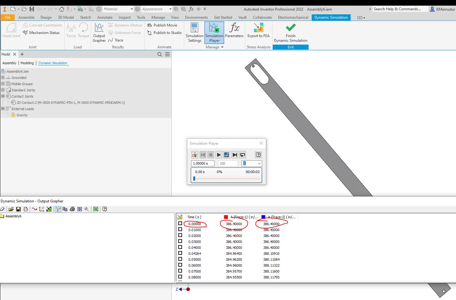
I modeled a simple arm hinged at top acting like a pendulum. I am trying to release drop the pendulum from an angle. Once I run the simulation and check the trace plots of acceleration @ time t=0 I see different acceleration numbers on different portions of the arm. I was expecting to see a CONSTANT 386.4 in/s^2 acceleration as the body is at rest at time =0. Whereas I see different g numbers at different points of the arm.


I have attached the model and also a screenshot showing different acceleration numbers at time t=0


Can you please explain what is happening?

0 Likes
Accepted solutions (1)
1,960 Views
17 Replies
Replies (17)
Message 2 of 18

swalton
Mentor
Mentor

I haven't opened the model, but looking at the screenshot...


It looks like Inventor is reporting the x and z axis acceleration components of the pendulum as the body swings in a radius.  I'm not sure if the results are in the global coordinates or in some local coordinate system. 

Steve Walton
Did you find this post helpful? Feel free to Like this post.
Did your question get successfully answered? Then click on the ACCEPT SOLUTION button.

EESignature


Inventor 2025
Vault Professional 2025
0 Likes
Message 3 of 18

KMamudur
Explorer
Explorer

Hello Steve,


The accelerations reported are both resultant accelerations. Not any component. Please see picture attached.

At time =0 when the pendulum is at rest shouldn't both the accelerations be =1g?


Thank you,

Karthik

0 Likes
Message 4 of 18

admaiora
Mentor
Mentor

Those numbers are correct.

That is not angular acceleration.

How can have those 2 points the same acceleration, they have different components and so different resultants (with same x,y,z reference)


The first point (below) for example:

ax is zero

ay start negative than positive

az start positive than negative


The second point (the upper) for example:

ax is zero

ay start negative than positive

az start negative than positive


They have different path/orientation.

Admaiora
Did you find this post helpful? Feel free to Like this post.
Did your question get successfully answered? Then click on the ACCEPT SOLUTION button.

_____________________________________________________________________________
Facebook | Twitter | Youtube

0 Likes
Message 5 of 18

KMamudur
Explorer
Explorer

Thank you for a quick response. 


Really a part that is in rest will have different accelerations along its shape?? See image below when I made my contact manually in dynamic simulation instead of importing contact from Inventor 3D model. I see same accelerations at time t-0 as I was expecting. 100% same geometry, like I said instead mating the arm with the pin in Inventor environment, I came into dynamic simulation and created my contact between the od of the pin and Id of the slot in the arm. NO OTHER SETTINGS WERE CHANGED


Can you explain this please? I can send you this modified assembly file again if need be.


Please see picture attached below. 


Thank you,

Karthik


0 Likes
Message 6 of 18

admaiora
Mentor
Mentor

"Really a part that is in rest will have different accelerations along its shape??"

>> Yes. At istant 0 the acceleration is already active while v is 0

Admaiora
Did you find this post helpful? Feel free to Like this post.
Did your question get successfully answered? Then click on the ACCEPT SOLUTION button.

_____________________________________________________________________________
Facebook | Twitter | Youtube

0 Likes
Message 7 of 18

KMamudur
Explorer
Explorer

So, you are saying a body at rest (Pendulum arm in this case) will experience different accelerations along at different locations on it. It is like a man standing still on earth in a bent configurations and his head is seeing x times more accelerations than his arms? I cannot understand that.


Even if I assume it as true for a moment, why did my 3rd simulations on the same arm yield same accelerations at every location of the arm while the arm is at rest?? How do you explain that? See the picture of the 3rd run attached again with this post.


0 Likes
Message 8 of 18

JDMather
Consultant
Consultant

@KMamudur wrote:

I was expecting to see a CONSTANT 386.4 in/s^2 acceleration


Constant? 

Shouldn't acceleration of a pendulum be a sine curve?


-----------------------------------------------------------------------------------------
Autodesk Inventor 2019 Certified Professional
Autodesk AutoCAD 2013 Certified Professional
Certified SolidWorks Professional


0 Likes
Message 9 of 18

KMamudur
Explorer
Explorer

When the pendulum is at rest @ time t=0 will it still be a sine curve? Should it not be a constant 1g= 1x386.4in/s^2?

0 Likes
Message 10 of 18

JDMather
Consultant
Consultant

@KMamudur wrote:

 1g= 1x386.4in/s^2?


Is the mass falling straight down without restriction 

or 

is the mass restricted to falling in a curve about a point?

(Translation and Rotational motion, not simple Translation motion.)


-----------------------------------------------------------------------------------------
Autodesk Inventor 2019 Certified Professional
Autodesk AutoCAD 2013 Certified Professional
Certified SolidWorks Professional


0 Likes
Message 11 of 18

KMamudur
Explorer
Explorer

Hello there,

@ t =0 the mass is at rest, or just starting to fall down. It starts to fall free and make contact with the fixed/grounded pin and then starts to swing/pivot about the pin as the pin is grounded and the MPC equations kick in. at time =0.000001~0 seconds I expect the freely falling arm to feel 1g load and not more. Also every point on the freely falling arm (before it touches the grounded pin) should see 1g load and not different value. Can you please open the assemblies that I sent and see it for yourself? I am attaching a picture showing 2 scenarios where inventor predicts different g's at different points on the arm @ t=0s and same g's at different points on the arm @ t=0s. I am also showing you the position at t=0s to avoid any confusion if you have not opened the model/.iam file.


Thank you for looking into this!!

0 Likes
Message 12 of 18

JDMather
Consultant
Consultant

@KMamudur wrote:

Can you please open the assemblies that I sent and see it for yourself? 


I see only the assembly that you Attached in Message 1 and first thing I noticed is that the mechanism was not constrained properly. I would expect to see Mate - Flush constraints between Planes and a Mate between Axis automatically converted to Revolution Joint (not a Cylindrical Joint) in Dynamic Simulation.


I do not see a second example with 2D Contact Joint.


-----------------------------------------------------------------------------------------
Autodesk Inventor 2019 Certified Professional
Autodesk AutoCAD 2013 Certified Professional
Certified SolidWorks Professional


0 Likes
Message 13 of 18

KMamudur
Explorer
Explorer

Please see both models attached. Let me know if @ time =0 the arms have to experience same or different accelerations across different locations on the arm. After it is in motion, different points will see different accelerations etc. But when they just start do you think they should be different? In Assy6 I am not putting constraints in Inventor, I am adding a joint in dynamic simulation instead and that gives me same accelerations at t=0.

Thank you,


Thank you,


0 Likes
Message 14 of 18

JDMather
Consultant
Consultant

In Assembly4a

you already have an imposed position change...

JDMather_1-1709296797138.png

No Friction on the Revolution Joint.

JDMather_2-1709296836444.png


Will only rotate about axis - no other motion involved.

JDMather_3-1709296894416.png


_____________________________________


In 2D Contact Joint - Restitution (bounce) and Friction.

JDMather_4-1709297006585.png

Translation in plane as well as rotational motion..


JDMather_5-1709297226612.png

and imposed Position change in all three...  (I should have screen capture at the Rotationl DoF, but you get the idea)


These are not even close to equivalent cases.

Not sure of your true Design Intent.


-----------------------------------------------------------------------------------------
Autodesk Inventor 2019 Certified Professional
Autodesk AutoCAD 2013 Certified Professional
Certified SolidWorks Professional


0 Likes
Message 15 of 18

KMamudur
Explorer
Explorer

Hello there,


Thanks for looking into it. My intent of this exercise is to see if the initial accelerations are being reported correctly. Even with those modelling differences between Assembly4 and Assembly6 shouldn't the initial accelerations not be the same ? My key question is this: "The arm is at under the influence of gravity= 1g at t=0, doesn't that mean every point on the arm at t=0 needs to read 386.4 in/s^2 till is starts accelerating further?"


Position (-~137.96 deg) shown above is correct as I intent to release/leave the arm starting from that position. I don't think friction input will affect the accelerations at time t=0s, correct me if I am wrong. Yes, in Assembly 6 it will pivot only about an axis, but again this should not affect the initial accelerations to which the arm is subjected to.


Can you tell me what I setting I need to change in Assembly4 to have it report 1g accelerations at t=0?


Thank you for taking the time to look into this. The actual model at hand is much more complicated. I am only showing a simpler model and thought of asking you about the discrepancy. 


Goal of all this:

To let the arm start at an angle (Say 25.1 deg to the vertical), ignore the friction, let is swing and see if the INITIAL ACCELERATIONS at t=0 = 1g at every point on the arm. Goal is not to create a model that captures friction, in plane /out of plane motion etc. Goal is also to understand what settings I need to change in the revolution joint (which is the only joint in Assembly4) to make that possible.


I appreciate your patience!

0 Likes
Message 16 of 18

Cris-Ideas
Advisor
Advisor
Accepted solution

Hi,

If arm is not allowed to move straight down (free fall) it will not show 1g acceleration through the part 


Your part in not "at rest". It is only in a state where V(t=0) =0, 

This is not equivalent to being at rest V(t) =0, a(t)=0.


For your part to be at rest you need to provide it with enough constrains to enforce it being stationary in your coordinate system of reference. 

If this was the case than your part could not move, and would not swing as you want.


To show 1g acceleration you need to remove constrains and let your arm fall straight down. 

If your intent is to simulate situation where your arm first drops some distance and than at some point in motion hists the pin and starts to swing, than in the beginning (free fall stage)  acceleration will be reported as 1g through the part. 


If pin constrain is active from the beginning of the simulation than acceleration will not be reported as 1g through, as part is not allowed to free fall, and therefore acceleration in each point will be different doe to accelerated rotational movement. 


Your part is NOT at rest in any point of the simulation. In order for it to be at rest it must have V(t) =0 AND a(t) =0

This is never true in your setup.


Cris

Cris,
https://simply.engineering
Message 17 of 18

KMamudur
Explorer
Explorer

Thank you!

0 Likes
Message 18 of 18

admaiora
Mentor
Mentor

Dynamic Simulation enviroment is quite complex and specific app laws.

It requires a robust medium/high knowledge of Inventor.

Admaiora
Did you find this post helpful? Feel free to Like this post.
Did your question get successfully answered? Then click on the ACCEPT SOLUTION button.

_____________________________________________________________________________
Facebook | Twitter | Youtube

0 Likes