Structural constraints in a crane hook

Structural constraints in a crane hook

Anonymous
適用対象外
3,890件の閲覧回数
22件の返信
メッセージ1/23

Structural constraints in a crane hook

Anonymous
適用対象外

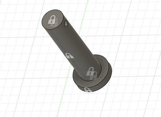
Good morning, we are dealing with the simulation toolbox in Fusion360, in particular for the static stress analysis. Anyway, we have some doubts related to the structural constraints: you can see in the pics attached the constraints that we have assigned. Namely, we have two loads, one applied on the hook (to represent the weight of the object transported) and one applied on the pulley (to represent the force of the crane).  

Can you help us in understanding if these constraints are correct or if it is better to make different decisions? Thank you in advance. 

解決済み
3,891件の閲覧回数
22件の返信
返信 (22)
メッセージ2/23

Anonymous
適用対象外

Here the pictures with the first three constraints. 

メッセージ3/23

Anonymous
適用対象外

Here the others constraints. 

メッセージ4/23

TheCADWhisperer
Consultant
Consultant

Can you File>Export your *.f3d file to your local drive and then Attach it here to a Reply?

メッセージ5/23

Anonymous
適用対象外

I have attached here the file. 

0 件のいいね
メッセージ6/23

TheCADWhisperer
Consultant
Consultant

What is this?

TheCADWhisperer_0-1630079821240.png

What is this?

TheCADWhisperer_1-1630079885960.png


These should be one body - why do you have modeled as two bodies?

TheCADWhisperer_2-1630079922605.png


0 件のいいね
メッセージ7/23

TheCADWhisperer
Consultant
Consultant

What is this?

This doesn't make logical sense?

TheCADWhisperer_0-1630080036045.png

This might last all of 3 seconds under load.

Why did you model as two bodies?


TheCADWhisperer_1-1630080087418.png

This should be one body - did you not look at my example posted earlier?

0 件のいいね
メッセージ8/23

TheCADWhisperer
Consultant
Consultant

Does Ctrl b (Cmd b) return any issues?

0 件のいいね
メッセージ9/23

TheCADWhisperer
Consultant
Consultant

Keep it simple.png

メッセージ10/23

TheCADWhisperer
Consultant
Consultant

We can progress to the advanced topic of FEA - but first the components should be corrected.

In FEA - these simple parts should be analyzed separately rather than as an assembly.

Section View.png


https://www.youtube.com/watch?v=tOwnqXsIiMw&list=PLp5izJt_zvN0KUccGh5OrgbNTZ_c4vYxs&index=19


TheCADWhisperer_0-1630082138825.png


メッセージ11/23

Anonymous
適用対象外

We have corrected the bodies, but we still have some doubts about the positioning of the constraints on the parts.

0 件のいいね
メッセージ12/23

TheCADWhisperer
Consultant
Consultant

Next we will analyze each body one-at-a-time.


Right click on each body and select Remove.

TheCADWhisperer_0-1630156621889.png


Right click on the Remove feature for the Hook and select Suppress Feature.

(By suppressing or not suppressing we can get one body at a time.)

TheCADWhisperer_1-1630156690995.png


0 件のいいね
メッセージ13/23

TheCADWhisperer
Consultant
Consultant

TheCADWhisperer_0-1630156795172.png

Delete all previous Constraints/Loads - you should have only on Constraint on the cylindrical face as shown above.

0 件のいいね
メッセージ14/23

TheCADWhisperer
Consultant
Consultant

Select SIMPLIFY

TheCADWhisperer_0-1630156942417.png


0 件のいいね
メッセージ15/23

TheCADWhisperer
Consultant
Consultant

TheCADWhisperer_0-1630156973079.png


Start a new sketch on the XY Plane.

0 件のいいね
メッセージ16/23

TheCADWhisperer
Consultant
Consultant

TheCADWhisperer_0-1630157058308.png

The load on the hook will contact the area of a chain or strap - we need to define the area of contact.

Create sketch as shown in image.

0 件のいいね
メッセージ17/23

TheCADWhisperer
Consultant
Consultant

Go to Modify>Split Face...

TheCADWhisperer_0-1630157153920.png

Use the sketch to split the contact face of the hook.

0 件のいいね
メッセージ18/23

TheCADWhisperer
Consultant
Consultant

Click Finish Simplify and then apply the load to the split contact face of the hook as shown...

TheCADWhisperer_0-1630157288517.png

Run the analysis for the hook.

Report back on the results.

TheCADWhisperer_0-1630157414826.png

Then we can move on to the next component...

0 件のいいね
メッセージ19/23

Anonymous
適用対象外

We have done the same analysis on the hook part. 

0 件のいいね
メッセージ20/23

TheCADWhisperer
Consultant
Consultant
解決済み

Right click create a New Simulation...

TheCADWhisperer_0-1630238307249.png

Suppress Remove of Body 15...

TheCADWhisperer_1-1630238471268.png


Select SIMPLIFY...

TheCADWhisperer_2-1630238596704.png

Create a sketch to split the clamping faces...

TheCADWhisperer_3-1630238799664.png


Split the top and bottom clamping faces...

TheCADWhisperer_4-1630238871327.png

TheCADWhisperer_5-1630238920887.png


Fix the clamping faces...

TheCADWhisperer_6-1630239039353.png


Apply the Bearing Load (be sure to select both faces at once).

Make sure the load arrows are pointing in correct direction (I had to Flip Direction).

TheCADWhisperer_7-1630239211599.png


Note that the Displacement is shown as exaggerated..

You could put it on Actual...

TheCADWhisperer_8-1630239416576.png


TheCADWhisperer_9-1630239536363.png

If the displacement was excessive (not in this case) I might increase the width of the bushing to limit the inward displacement.  Split faces for the bushing contact and add Frictionless constraints to the faces.


Next we can test the Pin.

Split the faces for contact with the bracket and with the bushing.

Add the Pin Constraints and the Bearing Load...

0 件のいいね