A custom gear shape design

A custom gear shape design

BillGEGHV
Advocate Advocate
2,761 Views
27 Replies
Message 1 of 28

A custom gear shape design

BillGEGHV
Advocate
Advocate

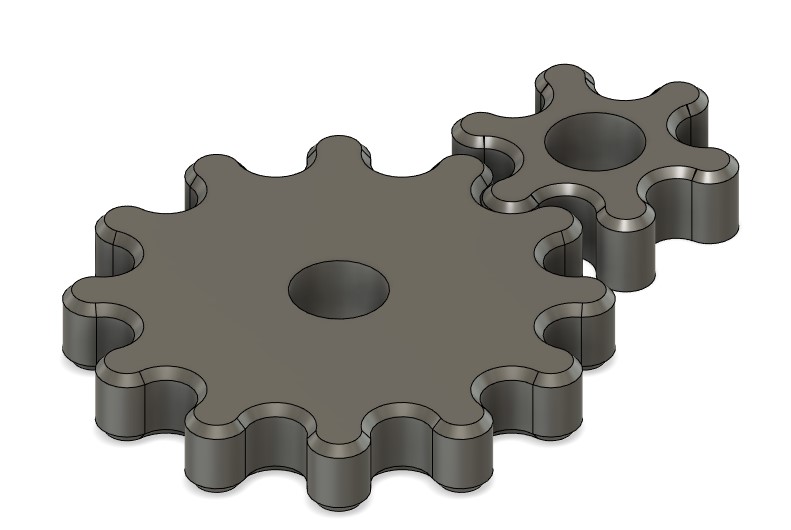
Hi All,  I'm wondering if anyone can give me any input on creating a simple custom gear/arrangement that I can change parametrically. The goal being to be able to change the tooth count and shape of teeth on the fly without having to redraw everything over and over. Im just not that good yet at constraints and perametics    ;  { 


2nd requirement is that the gear shape needs to be pretty close to what I have already, as the larger gear is actually a thumbwheel that will be turned by your thumb to make setting changes to a machine. SO the gear needs to feel confortible when turning by your thumb or finger. 


3rd requirement is the final gears need to be CNC machined from top and bottom ONLY in aluminum and are quite small so I will need to finish with 1/8 end mill to get into the pocket without any axial undercuts of the gear teeth.  


Any input would be appreciated. 

0 Likes
2,762 Views
27 Replies
Replies (27)
Message 21 of 28

BillGEGHV
Advocate
Advocate

I was thinking about using this nifty little program to get these gears done, then export and tweak the curves.  Thought I would share it its actually pretty darn versatile and really cool. 


https://woodgears.ca/gear/

0 Likes
Message 22 of 28

etfrench
Mentor
Mentor

You can export individual components using the "Save Copy As" command.  (Right click on the component in the Browser to bring up the Context menu.)

The pitch diameter of the gears should be at the center of the tooth circles.  If you add Revolute joints to your gears along with a Motion link, you'll see the gears won't mesh when they rotate.

Once you've defined the pinion gear (small gear), the driven gear's pitch diameter must be directly related to the tooth count.  The center to center distance should match the pitch circles radius (except for a backlash allowance).  One seat of the pants way to adjust backlash is to put a piece of paper between the gears (about .003").

Use formulas in User Parameters to control the tooth count, which in turn will control the pitch diameter.  Check the formulas in previous post. 

To draw one tooth form, you need to draw the two circles on either side of the tooth circle using a circular pattern with just those three circles.  Look closely at the sketch lines in the screencast.


ETFrench

EESignature

0 Likes
Message 23 of 28

BillGEGHV
Advocate
Advocate


Ive watched your screencast many times and have made several attempts to follow and copy what you are doing step by step but im not getting it. Any way you can make a narration of your steps I can follow along with? OR type it out?
Some of your mouse moves in the beginning steps are really hard to follow, the double clicks are beyond me, Are they on purpose? are you adding constraints? OR is it just the way you work? Maybe a drawing function I just do not know? Its confusing me? also really throwing me is it looks like you are backtracing over or drawing on top of the 1st line you draw, then double and even triple-clicking? Not sure what is going on there.

Other things Im not getting is the use of the formula at 1:39. Why and what is this for?

One thing to copy what you're doing and another to really understand Why and what you are doing so I understand it.

0 Likes
Message 24 of 28

etfrench
Mentor
Mentor

Screencast can make mouse behaviour erratic.  At the start of the first video, the Esc key wasn't exiting the line command, so it took a while to figure out what combination of mouse clicks and keystrokes would exit the command 😀

The formula was used to determine the circle size.  With a pitch diameter of .516 and 6 teeth(12 circles),  the radius is .516/2 and half of the tooth angle is (360/12)/2 which gives the tooth circle a diameter of .13355.    In the second video (which is the best one to follow) I entered the tooth circle diameter as a user parameter.  The DrivenAngle (Driven tooth angle) is ( 360 / ( DrivenTeeth * 2 ) ) * 1 deg.  This angle will be the same for any tooth size and changes by tooth count.  The second video shows starting from the tooth size and drawing the angle to get the radius of the pitch diameter, while the first video show drawing the radius of the pitch diameter and the angle to determine the tooth circle size.  Step through the timeline in  the attached file to get a better understanding of the process.


p.s. No microphone on the computer, so no talking videos 😂

ETFrench

EESignature

0 Likes
Message 25 of 28

BillGEGHV
Advocate
Advocate

IS there any way to walk through the timeline of a sketch to show me all the steps and how you drew it? That's what I REALLY need to see exactly what you're doing when you draw each step.  I want to learn how to do this but im now I'm leaning toward just using what you have provided, so in that case, I sure appreciate the file, thank you.  


Another thing I cant figure out 

On your sketch how would I change the origin to the common shared tooth for each gear so the tooth change and scaling happens at the common tooth not at the center of the gear center hole? 

0 Likes
Message 26 of 28

etfrench
Mentor
Mentor

Use a joint to position the gears.  The shafts the gears are located on need to be at the radius of the pitch diameters.


RoundGears2.JPG


Instead of hard coding the gear diameters, use the Pathagorean Theorem or the Law of Sines to calculate the radii of gears.


The controls to step through the Timeline are located at the lower left corner of the Fusion 360 window:

TWalker.jpg

ETFrench

EESignature

0 Likes
Message 27 of 28

BillGEGHV
Advocate
Advocate

Right "use joint"  Got it.  ;  )   DUH! 


BUT the buttons for the timeline only toggle through the features not a timeline for an OPEN sketch? OR dose it, if it does it's a feature I'm not sure how to use.  I just tried them with the sketch open and they do nothing.  

0 Likes
Message 28 of 28

etfrench
Mentor
Mentor

Close the sketch.  Click on the far left icon.  Clicking on the middle icon will play the file like a cd.  The icons on each side of the middle will move one feature either backwards or forwards in the timeline.  The far right and left icons move to the end or beginning.  You may need to turn the visibility of a feature on. Edit the feature to see what settings were used to create it.

ETFrench

EESignature

0 Likes