Scaling a Picture appears to create a non-uniform scaling of the Picture?

Scaling a Picture appears to create a non-uniform scaling of the Picture?

ecnels
Advocate Advocate
1,174 Views
15 Replies
Message 1 of 16

Scaling a Picture appears to create a non-uniform scaling of the Picture?

ecnels
Advocate
Advocate

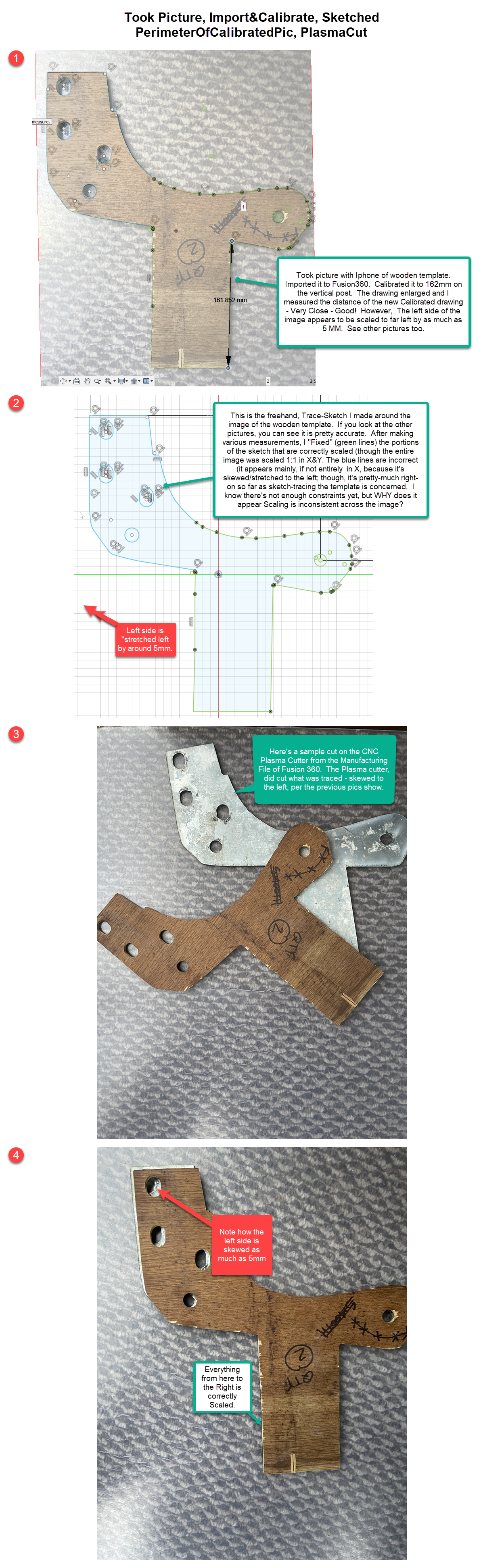
Enclosed, are several screenshots and a couple of pics of a wooden Template a person handed to me to create a metal part on our CNC Plasma Cutter.  I took a picture of the wooden template (as close to 90 degrees at the middle of the template as freehand picture-taking permits), then imported it into Fusion360, then measured the right-side post of the 'T' and entered that length in Calibrate.  Next, I simply free-handed with the line & arc sketch tools around the edge of the Calibrated Picture of the Template.  I checked a few line & hole lengths in the sketch, which were fine, so I cut it out on the plasma cutter.  It turns out that the left side of the picture has "grown" to the left about 5mm with that Calibration. (Note the last two pictures to see that difference, which IS being cut according to the sketch.  Since the sketch matches the outline of the wooden template per the Calibrated Picture, my assumption is something is wrong with the Calibration.  (Note: If the text in the enclosed .png file is too small to read, hold down the Cntrl Key and move your scroll wheel.


Ideas?  Thanks!

0 Likes
1,175 Views
15 Replies
Replies (15)
Message 2 of 16

ecnels
Advocate
Advocate

Instead of "Scaling" for the Title, it would have been more accurate to have written "Calibration", because that's what I did.

0 Likes
Message 3 of 16

davebYYPCU
Consultant
Consultant

That’s bad photography - you can tell by the shadows in the holes either side.


5mm distortion is camera error.

If you have the wooden piece to follow, why rely on the picture and not the timber piece.


Might help....


0 Likes
Message 4 of 16

ecnels
Advocate
Advocate

The reason for not using the wooden template is it requires a bunch of time-consuming measurements, but the idea of simply taking a picture, scaling it and sketching the perimeter would shave an hour off design to cut.

0 Likes
Message 5 of 16

davebYYPCU
Consultant
Consultant

How much time did you save?


0 Likes
Message 6 of 16

ecnels
Advocate
Advocate

The shadow in the holes is caused by the depth of the wooden template.  I'm not certain that makes it a bad picture to the tune of a 5mm skew; after all, I sketched off the top of the image (no depth).  Perhaps, I'm about to be surprised that a small angle on a camera, 1 foot away from this object creates 5mm skew on one side of center, but not on the other :).

0 Likes
Message 7 of 16

davebYYPCU
Consultant
Consultant

Humour me.

Calibrate the longest dimension from the wood bit, to the longest part in the picture, 

still got accuracy?


0 Likes
Message 8 of 16

ecnels
Advocate
Advocate

If this approach can be made to work cleanly, then it will EASILY shave a couple of hours measuring simple free-hand stuff like this.  This is not just about one job.  If you have some value to add, beyond elementary school sarcasm, I'm all ears and will appreciate it as I'm a busy man and don't want to waste my time or that of the productive people on this Forum.  Perhaps, it is that a slight tilt of a camera can make that huge of a difference or maybe something else is going on?  I'm asking for useful advice from other experienced users about the approach of using a calibrated picture trace.  What am I missing?

0 Likes
Message 9 of 16

davebYYPCU
Consultant
Consultant

Your missing Camera error, it’s well known.

Flatbed scan is better, but measured triangles are pretty quick.


Sorry to be a bother, Spending more time here is just holding you up. you can hurry up and throw them in the bin, or slow down and get it right - first time.


0 Likes
Message 10 of 16

ecnels
Advocate
Advocate

Here's some more info:  There are 4 different pictures, from my iphone, in this file.  They are taken at varying distances (1 to 4 feet vertically) and locations within the camera view-finder.  The camera is very close to level (based on using leveler software while snapping the picture freehand - but I'm confident it's under one degree).

- In the pictures, you'll see the orange rectangles, depicting the Calibration entry made for each independent picture.  This measurement is of the two points that I used for the Calibration Distance for that image.  You'll see that the freehand Calibration I'm doing, over multiple pictures is generally less than 1 mm (actual part length here is 162mm), so Calibration is pretty consistent - well within the requirements here of roughly 2mm.

You'll also see the white rectangles, depicting the longest measurement across the part (the Diagonal).  Those appear to be consistent in two groups (roughly 448mm and 441mm), but here's a question:  WHY are all four of those measurements so far off that actual part distance of 429mm?  That seems way off for such a relatively small distance with a mostly level camera?  Twelve to fourteen mm for that distance seems like more than camera positioning?  Is it?

0 Likes
Message 11 of 16

wmhazzard
Advisor
Advisor

You problem comes from the camera. Google Parallax for an answer. 

0 Likes
Message 12 of 16

TheCADWhisperer
Consultant
Consultant

Can you File>Export your *.f3d file to your local drive and then Attach it here to a Reply?


0 Likes
Message 13 of 16

davebYYPCU
Consultant
Consultant

You problem comes from the camera. Google Parallax for an answer. (or Fish Eye and you got some in those photos)


0 Likes
Message 14 of 16

ecnels
Advocate
Advocate

Sure - Here's the F360 File

0 Likes
Message 15 of 16

ecnels
Advocate
Advocate

If you were measuring this part and transferring it to CAD for simple cutting of the holes and perimeter, how would you approach that task?  This part was created freehand by the user.  It is not square.  The lines are not particularly straight (versus typical machining design) and multiple radius's are combined in the same "arc".  Perhaps the user will like it if I "straighten this out for them" this time, but another time they may not want me changing their intent.  If I assume that some accuracy improvement will be appreciated by the user (I have in this instance), then how would you approach measuring this part via triangles as you've mentioned?  Thanks!

0 Likes
Message 16 of 16

davebYYPCU
Consultant
Consultant

madtcl.PNG


Dimension the construction lines.  Start from known area and work away from there.

You might need some others, but it's how I do it.


Might help....

0 Likes