Note: This article is written and published in Portuguese and is a translated version of the original published here.
Executive Summary
Project georeferencing in BIM is a process that requires careful planning and organization before any modeling begins. The fundamental premise is that the correct initial configuration takes a few minutes, while correcting placement errors in later stages can consume days of work and compromise the integrity of federated models.
It is important to realize that here in this article I describe my method: one that works. This does not mean that others do not also work, so it can be adjusted and adapted to your work process.
Central points to successful georeferencing include:
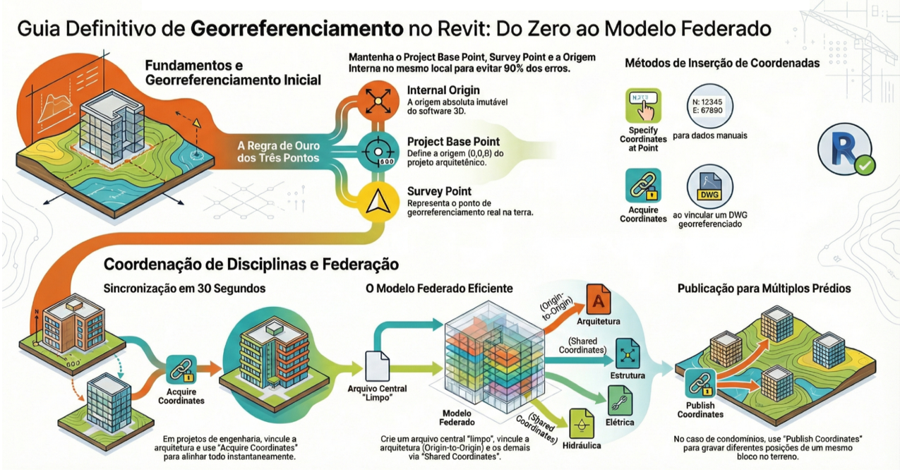
- The Three-Point Rule: Keeping the Project Base Point, the Survey Point (Survey Point) and the Internal Origin (0,0) in the same place at the beginning of the project solves 90% of coordination problems. It is not mandatory, but it simplifies the process.
- Coordinate Workflow: The architectural project acts as the master of coordinates, from which engineering projects (strategic and complementary) acquire positioning information.
- Federated Models: The use of shared coordinates and links enables the creation of lightweight federated models, making it easier to coordinate and manage multiple buildings on a single site.
- IFC Export: There is no universal configuration, but standardization via IFC4 and adjustment of the coordinate base are crucial for interoperability.
- Initial Setup
The foundation of a georeferenced project in Revit lies in managing three reference points:
- Project Base Point (Circle): Defines the local origin of the project.
- Survey Point / Survey Point (Triangle): Represents the actual georeferencing point on the Earth’s surface.
- Internal Origin / Location Line (arrow gizmo): This is the absolute zero point of the software, common to any 3D program.
The Universal Strategy
To ensure the model is properly federated, the primary recommendation is to keep these three points in the same location when starting the file from an architectural template. The project should preferably begin from a building corner or a site corner positioned on these points.
"Keep the three points in the same place and you will solve 90% of any problem that may occur in your georeferenced project. Simple as that."
--------------------------------------------------------------------------------
- Architectural Georeferencing Methods
There are two main ways to define coordinates in the architectural master file:
2.1 Manual Coordinate Specification
Used when the professional already has coordinate data (North/South, East/West, Altitude, and Angle from True North) from a survey or Google Earth.
- Path: Manage > Coordinates > Specify Coordinates at Point.
- Attention to the “Clip”: When manipulating the Survey Point (Triangle), ensure the clip icon shows a red dash (unclipped). This allows assigning coordinates without accidentally pulling and offsetting the entire 3D model.
- Extra Tip: Use the Manage > Location tool to define the exact geographic position of the site. This is critical not only for documentation, but also for the accuracy of solar studies and thermal simulations.
2.2 Acquisition via DWG File
Used when there is a georeferenced topography file in CAD (municipality or surveyor).
- Insertion Procedure: When inserting the CAD, use the Center to Center option. Even if the file appears far from the origin in CAD, Revit will maintain the coordinates internally.
- Adjustment: Move the DWG to align the site with the Revit project, then use Acquire Coordinates from the CAD file.
- Workflow for Engineering Projects and Complementary Disciplines
For engineering disciplines (structural, plumbing, electrical), the georeferencing process is simplified and should be completed in seconds:
- Template: Start the file using the discipline-specific template.
- Link: Insert the architectural link using the Origin to Origin option.
- Acquisition: Go to Manage > Coordinates > Acquire Coordinates and click the architectural link.
- Verification: Use the Spot Coordinate tool to confirm the values match those of the architecture.
--------------------------------------------------------------------------------
- Project Correction and Coordinate Publishing
If an engineering project was modeled with incorrect coordinates, correction must be done from “outside in”:
- Open the Architecture file.
- Insert the engineering project (link).
- Move and rotate the engineering model into the correct position over the architecture (millimeter precision).
- Go to Manage > Coordinates > Publish Coordinates and click the engineering file.
- When saving the architectural file, Revit will prompt you to save the new coordinates to the linked engineering file.
--------------------------------------------------------------------------------
- Management of Multiple Buildings and Sites (Campus/Resort)
In projects with multiple towers or identical blocks on the same site, the workflow is advanced:
- Environment/Site File: Create a central file for the site (Urban Planning).
- Building Link: Insert the building file (e.g., Block A).
- Duplication: The link can be copied multiple times to different positions on the site.
- Named Positions: For each copy, use Publish Coordinates to create specific names (e.g., Building 01, Building 02).
- Internal Storage: The single building file will internally store all different geographic locations defined in the site file.
--------------------------------------------------------------------------------
- The Federated Model
The federated model is a coordination file that brings all disciplines together for compatibility and visualization. It can be created in Revit, Navisworks, or directly in the CDE. How does it work in Revit?
- Creation: Start a new file (no template, metric).
- First Step: Insert the architecture (Origin to Origin) and acquire its coordinates.
- Other Disciplines: Insert the remaining files (Structure, MEP) using Shared Coordinates.
- Advantage: The federated file is extremely lightweight (around 400 KB), acting only as a container for links, while original files retain their full size in MB.
--------------------------------------------------------------------------------
- IFC Export Strategies
Exporting to IFC (Industry Foundation Classes) is vital for interoperability, but requires specific settings to ensure correct positioning.
Recommended Export Settings
- Version: IFC4 (specifying discipline: Architecture, MEP, or Structure).
- Check “Export linked files as separate IFC files”. Crucial for maintaining federated model organization and avoiding oversized corrupted files.
- “Export only elements visible in view”. What is not visible should not be exported, avoiding geometric clutter in IFC.
- Properties: Include Property Sets, base quantities, and materials.
- Level of Detail: Set to “High”. According to Revit technical standards, this preserves openings, complex connections, and modeling details without excessive processing load.
- Troubleshooting and Correction Protocols
When models are developed with incorrect coordinates, the Inverse Correction Flow is applied.
Centralized Correction Execution
- Open the Architecture file (Source of Truth).
- Insert the misaligned engineering link.
- Manually position the engineering link over the architecture (millimeter precision in X, Y, Z, and rotation).
- Go to Manage > Coordinates > Publish Coordinates and click the engineering link.
- Cleanup: In Location > Site, delete all obsolete or duplicate coordinate instances. Perform this only if publishing coordinates is blocked.
- Save (Required): Accept the prompt to save the new position to the linked engineering file.
Trial and Error Tip: There is no universal rule. Different software (Archicad, TQS, etc.) interpret coordinates differently. Always export two IFC versions: one using Shared Coordinates and another using Base Point oriented to True North. Test both in the target software.
- Validation: The Federated Model and the Real Test
Never send an IFC to the coordinator without first validating the export. The real test is performed by creating a Federated File.
- Create a new project in Revit.
- Select None as the template and choose Metric units to ensure a 100% clean environment.
- Link IFC and RVT files and verify perfect alignment.
Final Export Checklist
- [ ] Was the Internal Origin (absolute 0,0) respected as a safety point?
- [ ] Are the three points (Base, Survey, Origin) aligned according to the “Golden Rule”?
- [ ] Is the export Level of Detail set to High?
- [ ] Are the top 5 Property Sets checked?
- [ ] Was the Reload From test performed in the federated file?
Remember: A well-executed 30-second coordinate setup process saves days of frustrating corrections. Accuracy in georeferencing is the hallmark of an elite BIM coordinator.
Mind Map – Georeferencing and Coordinates Master Guide in Revit
Videos and Guides
00 Introduction https://youtu.be/MozizrnbW9I
01 Key Principles https://youtu.be/VFFbS1oRFcY
02 Architecture Project https://youtu.be/CqGJJxx8xXU
03 Project Location https://youtu.be/YrlTdm598KE
04 Projects Engineering https://youtu.be/TV6HjFsG8Ro
05 Correcting Designs Engineering https://youtu.be/4bmM8yBkKXo
06 Advanced Multi-Project https://youtu.be/H2cTFei3gd8
07 Federated Model https://youtu.be/NMhlUf49qFY
08 Exporting IFC https://youtu.be/q_voMrN-zY4
Video Summary of this article: Dominando_o_Georreferenciamento.mp4
Georeferencing Review: Revit_Georeferencing_Playbook.pdf
Guide for Georeferencing projects: Guia_para_Georreferenciamento.png
www.instagram.com/alan.araujo.revit
About the Author
Alan Araújo
| |
|
Architect – Tec. Buildings
Master BIM + RA
Training / Lectures – Brazil
Graduate Coordinator BIM
Expert Elite – Autodesk
|
|


You must be a registered user to add a comment. If you've already registered, sign in. Otherwise, register and sign in.