Slad doesnt connect with the bars! Contour points ignore nodes

Slad doesnt connect with the bars! Contour points ignore nodes

Anonymous
Not applicable
1,787 Views
12 Replies
Message 1 of 13

Slad doesnt connect with the bars! Contour points ignore nodes

Anonymous
Not applicable

Hello, the problem is that my horizontal slab doesnt connect with the beam and other slab, somehow it has no support,i used contour in nodes, but it doesnt connect..so i got crazy displacesment and wrong maps, i tryed detail correction but it didnt work. I tryed to make unhorizontal slab as well, didnt work. And the other nodes on other slab works ok, and i created it by coping, and somehow they get out of the system. 

Please any advise

Thank you.

0 Likes
Accepted solutions (1)
1,788 Views
12 Replies
Replies (12)
Message 2 of 13

Rafacascudo
Mentor
Mentor
Can you send the model?

Rafael Medeiros
Did you find this post helpful? Feel free to Like this post.
Did your question get successfully answered? Then click on the ACCEPT SOLUTION button.

EESignature

0 Likes
Message 3 of 13

Anonymous
Not applicable

Yes, here

 And also maybe you could help me to understand how avoid the situation that i got at the following picture.

Thank you

0 Likes
Message 4 of 13

Rafacascudo
Mentor
Mentor
Accepted solution

the problem of not connected panels is because these 2 panels and the large one between them are not in the same level as the others. If you raise the number of decimals ,you will see that they are on Z=3.0985 , while the others are on 3.1000m.

Also many of your beams-slab connecting bars have not the correct Z coordinate(3.1000m) .


There is also some bad meshing spots due to innacurate small connectings bars position.

bad meshing.jpg


Also , the positive moment on the slab where you should be expecting a negative one ,is probably due to a "weak " supporting  beam not strong enough to support the slab the way you need/want .

weaker beam.jpg

Assign a stronger section to this beam and surely the situation of this slab will improve


Model with model/meshing corrections attached


You may watch the excelent webinars gave by Artur and Rafal . There are 2 (webinars 1 and 2) about good meshing practices and how to correct the problems on


Build your Robot Structural Analysis IQ - YouTube

Rafael Medeiros
Did you find this post helpful? Feel free to Like this post.
Did your question get successfully answered? Then click on the ACCEPT SOLUTION button.

EESignature

Message 5 of 13

Anonymous
Not applicable

Thank you so much , and these webinars are very helpful!

Although i changed a a section for that beam, and made a correction with offset, but the slab still got that positive moment, and the other problem appear in the contact of two panels nodes11.png Th33.pngThese nodes have the biggest moment .

Did i make any mistake, or i need to strengthen structure? Should i use a brackets at the beams for avoiding this concertation in the slab?

I attached corrected model.

Thank you for your time.

Regards

0 Likes
Message 6 of 13

Rafacascudo
Mentor
Mentor

Antonina ,


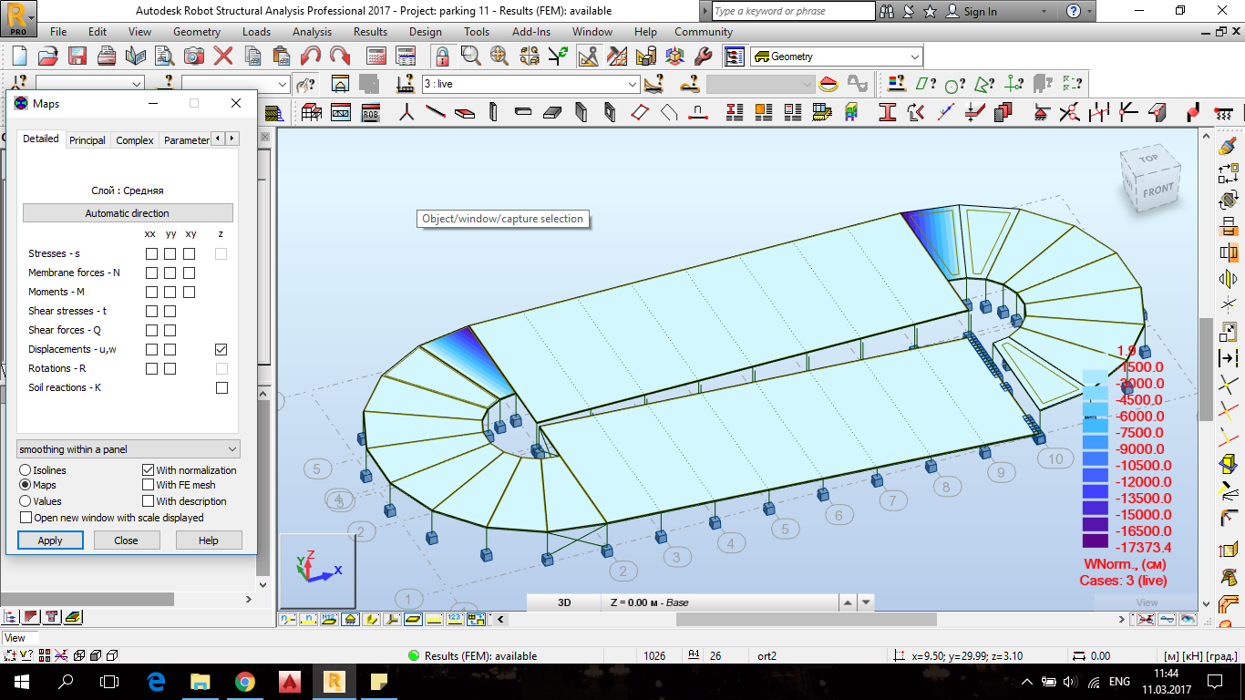
1st of all all ,you need to understand what the "direction" on Maps results dialog means.


   After you set the "direction" , It will give the direction of all "xx" results like Nxx ,Mxx,Qxx ,etc .


   If you choose "automatic" direction , which is the default  , "xx" results will in the direction of the each panel X local axis !!!


Looking at your current panels local axis system , it´s not a good idea to set "automatic" as a direction to  your panel maps.


Automatic direction on panels.jpg

You can see ,that for some neighbour panels the maps will be giving forces on perpendicular directions , Which is dangerous and can lead you wrong interpretation and ultimately to design mistakes.


Other than that the panels Z axis are also pointing  to different directions. It´s a good practice to keep them all pointing to the same direction

local Z axis down.jpg


I corrected the axis directions . The panels in the curves , I made the local X axis paralel to the outer edge. All Z axis pointing up

corrected panel local axis.jpg


Then , this way , on the curve the "xx" forces will be aproximately in the circunferencial direction and the "YY" forces will be the radial ones.


to get exact results on the curves (one at a time!!!) ,you can choose the polar direction and give the exact center of the circle.


polar direction.jpg


As all your slabs are orthotropic , setting the right panel local axes can make you set just one thickness for all slabs and set the orthotropy direction as " automatic" as it will obey the panel local X axis.


Below you can see that with the correct panel  local axes  , it seems to be the same result ,but now with correct signals and it gets more "friendly" using "global smoothing" setting

correct result.jpg   global smoothing.jpg


Rafael Medeiros
Did you find this post helpful? Feel free to Like this post.
Did your question get successfully answered? Then click on the ACCEPT SOLUTION button.

EESignature

Message 7 of 13

Anonymous
Not applicable

Thank you so much for so detail explanation!!! 

Now i understood what was my mistake from the very beggining! I changed the axes and used polar system, and i got exact result as you did.


 1.png12.png

So i guess that i need to ignore the moment in that points, and for manual checking of M and Q for the slab , use the forces that appear in the largest panel? And I'll stregthen the beam sure. Also i'll change the area of bars for reinforced concrete to avoid displacements that i got now.

Thank you again for your time, my apology if my questions are too trivial.


0 Likes
Message 8 of 13

Rafacascudo
Mentor
Mentor

Your inclined straight slab is still with Z local axis pointing down. That´s why in your last picture moment Myy shows diferent colours/signals on the panel edge neighbour to the curve

Rafael Medeiros
Did you find this post helpful? Feel free to Like this post.
Did your question get successfully answered? Then click on the ACCEPT SOLUTION button.

EESignature

0 Likes
Message 9 of 13

Anonymous
Not applicable

Understood, im sorry, my inaccurate mistake , i also changed the weak beam  so i got this: to ignore.png

Do I need to ignore the moment (=255;364) in that points, and for manual checking of M and Q for the slab , use the forces that appear in the largest panel?  My slab is composite.

Thank you.


0 Likes
Message 10 of 13

Rafacascudo
Mentor
Mentor

Some days ago ,someone(sorry ,tried to find who to give the credit ,but couldn´t) posted a very interesting link about these concentration forces/stresses spots.


https://br.comsol.com/blogs/singularities-in-finite-element-models-dealing-with-red-spots/


Also , What I usually do is to get the intended force across a 1 meter panel cut section , so we can get an average value. In your case something like this.


panel cut 1meter.jpg


When you choose "local of the cut" direction  this means that Myy is the moment along the cut and Mxx are the moments across the cut . So for Mxx ,the integral value is the total moment in the whole length of the cut ,in this case 1 meter ,125,90kNm/m , much less than the spike value of 333kN.m/m


Rafael Medeiros
Did you find this post helpful? Feel free to Like this post.
Did your question get successfully answered? Then click on the ACCEPT SOLUTION button.

EESignature

0 Likes
Message 11 of 13

Anonymous
Not applicable

Thank you for the article, found it very useful, so i'll try to interpret moments in the angles. And will try your advise for this.

Sorry for so many questions, hope it will be the last one: I copied 1 level with frozen mesh but i got an error with a mesh on the 5th floor and absolute crazy forces when i tryed to copied only 1 level. The loads i put are only live and self -weight. crazy momemts.PNGisolated nodes.PNG

Also Robot says that i have isolated nodes, but i checked the places and there are nodes from the 1 level, and they cant be isolated.

If I may ask could you check my model please and say what i did wrong , I only copied levels.

Thank you very much for your help.

0 Likes
Message 12 of 13

Rafacascudo
Mentor
Mentor

The 5th floor(top one) is just a roof?


Lots of errors due to imprecise copying


problems with the panels on the top floor were the cause of incoherent mesh.

error.jpgmesh error.jpg

The above picture problem(old mesh not fitting) ocurred on all right curved slabs on all levels


Instabilities warnings  on many nodes of small bars due to wrong release . Rx is the torsional release(releases are set on the bar local axes

rx release on both ends.jpg

Do theses bars need really to be released?


Many of theses small bars are now "alone" , not connected to the slab above giving lots of stability warnings.


So I deleted the releases on all small bars  and ALL instabilities warnings are gone!!!

I think you don´t need those releases as the small bar is a 1cm diameter solid bar and will not be able to "carry" significant moment from the slab above to the beam below.

Also , some of your bracings were also with rxy-rxy releases giving very large displacements . I changed to ryz-ryz as probably you wanted to release the bending moments.

Also some supports on high levels and gaps on the columms on the curves and 2 on the inclined slab

high supports.jpgcolumm gap.jpg


All isolated nodes also were deleted.


Are these supports right??

weird support line.jpg


Model corrected attached


Rafael Medeiros
Did you find this post helpful? Feel free to Like this post.
Did your question get successfully answered? Then click on the ACCEPT SOLUTION button.

EESignature

Message 13 of 13

Anonymous
Not applicable

I see now clear all mistakes, can't believe that i sent here so imperfect model.

Thank you very much for your advices, you helped me a lot.

Best regards

0 Likes