Can I use RSA to design (reinforcement) this concrete wall with door openings?

Can I use RSA to design (reinforcement) this concrete wall with door openings?

Anonymous
Not applicable
4,734 Views
26 Replies
Message 1 of 27

Can I use RSA to design (reinforcement) this concrete wall with door openings?

Anonymous
Not applicable

Hi all,


Sadly, I'm not using Robot much after finishing school and starting work as an engineer, but I now have a project where I hope to be able to use it some more. I tried solving this today with FEM Design, but I wasn't quite happy with the results and thought it was hard to use. I wanted to go straight to Robot, but had some technical issues acessing it. I hope to be able to solve this with Robot now.


I'm attaching picture of a wall. There's horizontal wind force at the top and a compressive force on one side and a tensile force (not so easy to see on the picture) on the other side.


Is it possible to get Robot to calculate reinforcement based on a simple model like this? 


If so, could anyone please give me some pointers or advice on how to proceed? Adding loads and making the model is easy. Just not sure after that.


1. Which module should I use?


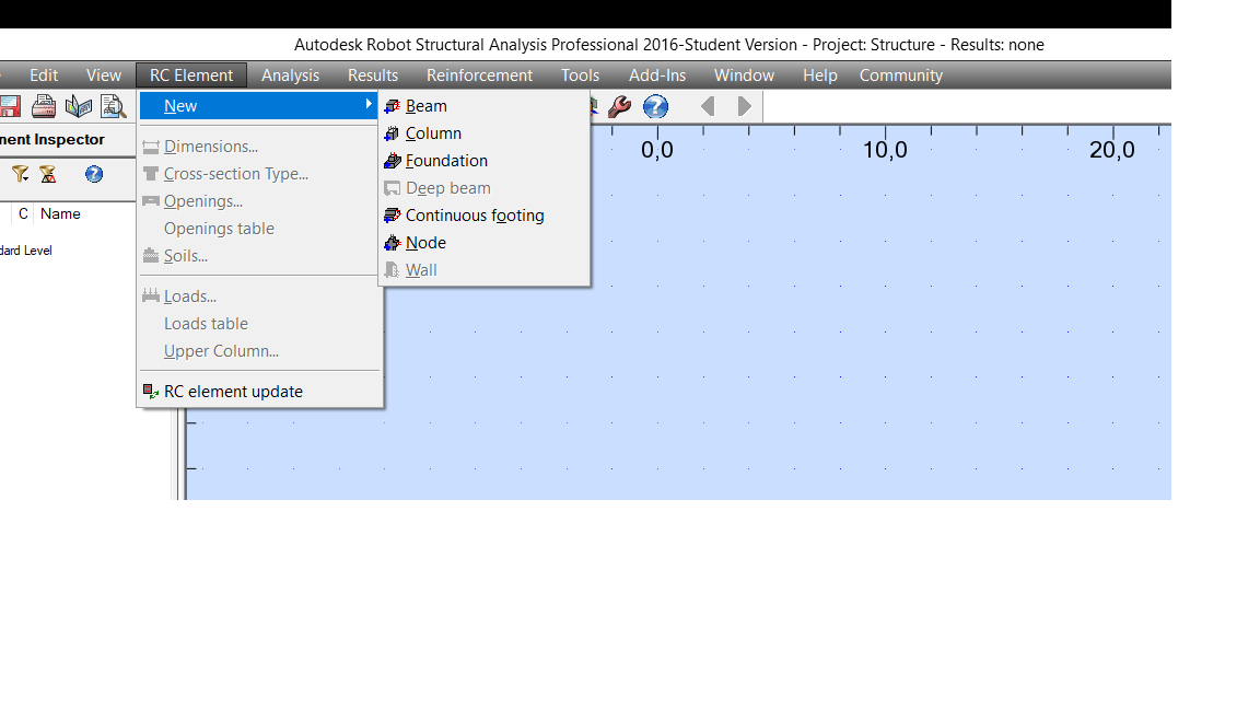
I first tried to open the RC Elements Design, but the option "Wall" under new RC Element is not available.


Could I use other modules if this one isn't available?


Thanks very much in advance! 🙂 


PS: I'm using EDUCATIONAL version at home. Is that why Wall isn't available?


My office have a license or two, but I won't be able to access it until over the weekend and was hoping to do this tomorrow. 


0 Likes
4,735 Views
26 Replies
Replies (26)
Message 2 of 27

Refaat
Advisor
Advisor

Hi @ RSA_Student


I hope the attached captures will be clarified your inquiries.


Refaat


222.jpg


000.jpg


111.jpg


Message 3 of 27

Anonymous
Not applicable

Hi, Refaat,


Thank you. I tried just now, but couldn't quite get it to work.


Did you first create the wall in "Shell Design" and then somehow import that wall/model into "RC Element Design"?


The wall I attached a picture of was created in the "Building Design" module as it's the one I'm most used to. I now tried to import this into RC design by selecting "Results" -->  "Provided Reinforcement of RC Elements". 


But I doesn't seem to work...


Thanks for any help. 🙂 


0 Likes
Message 4 of 27

Anonymous
Not applicable

When opening the RC Design module, it seems like I can't access the wall option.


Is this because I'm using the educational version at home or because something else is wrong? 


Wall_Missing.png


It would be great if I could get results similar to this video for the wall I'm designing:

https://www.youtube.com/watch?v=Vv4N9af8R9I


If so, I will for sure start using Robot a lot more for RC design.

0 Likes
Message 5 of 27

Refaat
Advisor
Advisor

Hi @ RSA_Student


Please, take a look to my quick video. Mind that (Both shell & building design module) can be used for RC walls modelling.


Note:


 If you don’t want to consider out of plane moment on the wall (bearing wall) then it is advisable to design your wall as panel (required and provided reinforcement) based on the internal forces in the wall.


Refaat


Message 6 of 27

Anonymous
Not applicable

Hi, Refaat,


Thanks a lot. Your efforts are really appreciated. 🙂 


Sadly, I get trouble when going from the design module to the RC inspector. I'm attaching pictures. It seems like it automatically goes to BEAM, not wall. I also get a design code error...


Maybe the Wall Design ain't possible with the Student version after all? I tried searching it, but couldn't find anywhere in the Robot documentation that says this isn't possible with the student version. Up until now, I've felt the student version has full functionality.


If I define the wall as a panel, it's imported as a slab. But I can't see no wall. Third picture attached.


I should be able to access a licensed version tomorrow at work...


Best regards.

0 Likes
Message 7 of 27

KillianPMG
Enthusiast
Enthusiast

@Refaat


Thanks for simple video.


I have a question, if i wish to model a wall which goes from foundation up to level 5. it is restrained at each floor level by slab.


How do i tell robot that it is restrained at each floor so that robot uses the correct effective length when designed wall for compression buckling,


Regards


Killian

0 Likes
Message 8 of 27

KillianPMG
Enthusiast
Enthusiast

@Anonymous

@Refaat


I have same errors as RSA student unformtunatley

0 Likes
Message 9 of 27

KillianPMG
Enthusiast
Enthusiast

@Anonymous 


Having played with this ore, if you change to the aci code before  running the analysis it works.


@Refaat is it not possible to design for openings using eurocode ??


Also, is it ok to remove left and right boundary elemnts and just enter 0 into the boxes. i do not want a pier with links at the end??


When i do this i get a warning, can this be ignored???


EDGE REINFORCMENT HAS NOT BEEN GENERATED!!


0 Likes
Message 10 of 27

Rafacascudo
Mentor
Mentor

Watch webinar 5 on Build your Robot Structural Analysis IQ - YouTube

Rafael Medeiros
Did you find this post helpful? Feel free to Like this post.
Did your question get successfully answered? Then click on the ACCEPT SOLUTION button.

EESignature

0 Likes
Message 11 of 27

Anonymous
Not applicable

Hi, Rafael,


I did watch that webinar, but unless I missed it, it doesn't explain the troubles I'm describing above.


Best regards.

0 Likes
Message 12 of 27

Artur.Kosakowski
Autodesk Support
Autodesk Support

Hi @Anonymous


Mind that the RC Wall module is available for French EC2 (NF EN) and ACI codes only.


If you find your post answered press the Accept as Solution button please. This will help other users to find solutions much faster. Thank you.


Artur Kosakowski
Message 13 of 27

Refaat
Advisor
Advisor

Hi @ RSA_Student


Please ,  your model ?


Refaat


0 Likes
Message 14 of 27

Refaat
Advisor
Advisor

Hi @ KillianPMG


How do i tell robot that it is restrained at each floor so that robot uses the correct effective length when designed wall for compression buckling,


Use supports ( the degree of freedom based on your assumption ) , on other hand according to how to execute the wall slab connection at  the site construction  .


@Refaat is it not possible to design for openings using eurocode ??


Yes. That is why it is advisable to design RC walls as panel ( required & provided reinforcement ) if out of plane moment doesn’t consider in your calculation.


Also, is it ok to remove left and right boundary elements and just enter 0 into the boxes. i do not want a pier with links at the end??


When i do this i get a warning, can this be ignored???


Check , ACI requirements.


Refaat


Message 15 of 27

Anonymous
Not applicable

Artur, 


Why is that? I suppose I can use the French EC2 then. It shouldn't be much of a difference, IMO.


Refaat,


I do not have access to it now, but I can upload it tomorrow.


Thank you for your interest and help with this. 🙂 

0 Likes
Message 16 of 27

Artur.Kosakowski
Autodesk Support
Autodesk Support

Hi @Anonymous


I'm sorry but I'm not able to tell how much these two codes are different for RC Wall design Smiley Sad


Artur Kosakowski
Message 17 of 27

Anonymous
Not applicable

Hi all,


I haven't been able to look into this until tonight, but managed to get a step further now, I think. 🙂 I have now been able to export the wall to RC Design and actually have it recognized as a wall. 


1. Design code


I did change to the French EC2 and that might have done the trick. 


What I meant Artur is that Norway and France probably doesn't differ that much as the whole idea with the Eurocodes is a design code that can be used all over Europe. We consider Robot supplemental calculation anyway, so this is ok.


2. Error


"In calculations according to the classic method openings are not taken into account" 


What does this mean? 


Most of the reason we're doing this in Robot is because of the effect of openings in the wall. If not, hand calculations are just as easy. 


3. Horizontal reinforcement in the zone is insufficient


This error code is also a little odd. Required area and provided area is 0 both? So, should be sufficient?


4. Using this information


Do I simply read the sheet "Wall reinforcement" and find necessary rebar from the tables? 


I might figure this one out on my own tomorrow, but I was a little puzzle right now as how to best make use of this calculation.


Thanks in advance for any help! 🙂 


Attaching model and error screenshot.


Best regards.

0 Likes
Message 18 of 27

Anonymous
Not applicable

@Refaat


Note:


If you don’t want to consider out of plane moment on the wall (bearing wall) then it is advisable to design your wall as panel (required and provided reinforcement) based on the internal forces in the wall.


*


Is this as simple as changing from wall to panel in the object inspector? 


I probably don't want to consider out of plane moment on the wall. Also, I might want to restrain the wall for out of the plane bending at mid point. But I suppose I can adjust that with a support.


0 Likes
Message 19 of 27

Anonymous
Not applicable

I updated my model with a pinned support at the midpoint in Z direction since the wall is joined with another element there to prevent buckling.


I also added the loads and load combination I'm interested in exploring (4: shear + compression/tension).


But, when trying to export the model to the RC design module, I get an error. See attachment. 


I've tried modeling a similar wall and I get the same result. I use the design code NF EN.


Any advice? 


It would be great to be able to use Robot to dimension these walls, but if I can't get it to work, I might have to use other methods/software. 


Thanks for any help! 🙂 


Attaching model and screenshot of error.

0 Likes
Message 20 of 27

Artur.Kosakowski
Autodesk Support
Autodesk Support

Hi @Anonymous


Mind the boundary conditions:


RC Deep Beam vs RC Wall.PNG


If you find your post answered press the Accept as Solution button please. This will help other users to find solutions much faster. Thank you.


Artur Kosakowski
0 Likes