Help Needed with Creating Elbow Family in Revit (New Piping Drafter)

Help Needed with Creating Elbow Family in Revit (New Piping Drafter)

lupacat
Community Visitor Community Visitor
408 Views
24 Replies
Message 1 of 25

Help Needed with Creating Elbow Family in Revit (New Piping Drafter)

lupacat
Community Visitor
Community Visitor

Hi everyone,
I’m a new piping drafter, and I’m currently working on creating a new pipe fitting family in Revit, following the pipe specifications from the material supplier.

I’ve already created the parameter CSV file and imported it into Revit. The units are set to millimeters, and the new family uses the Metric Generic Model. Everything seems to be going smoothly until I got stuck while entering the formula in the "Outer Diameter" dialog.

I don’t have any knowledge of Dynamo or programming in Revit, so it’s really difficult for me to create a new family in Revit.

My questions are:

  1. Formula for Outer Diameter:
    I’m unsure how to input the correct formula in this dialog box. Could anyone show me the correct formula to use? Also, how many formulas do I need to input to complete this new elbow family? I would greatly appreciate it if someone could walk me through the steps, one by one.

  2. Dynamic Data for Pipe Fittings:
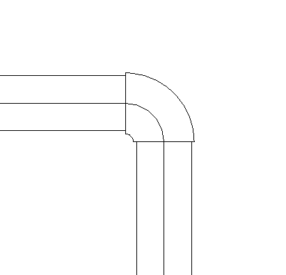
    The pipe fittings come with a lot of dynamic data for each type. For example, the Elbow 90-degree Sch. 10S has 15 types, and the inside diameter and thickness values change based on the outer diameter. I believe it’s possible to create a new elbow family where these values update automatically, but I’m not sure how to do this.

  3. Ideal Elbow Family Model:
    In my ideal model, when I select the Sch. 10S elbow in Revit, the type selector in the properties palette would allow me to choose from 15 different elbow sizes, depending on the specific requirements.

  4. Attachments:
    I’ve attached the CSV file and a screenshot for reference. Any advice or guidance would be greatly appreciated! Thank you in advance!

0 Likes
409 Views
24 Replies
Replies (24)
Message 2 of 25

russellvee
Advocate
Advocate

Creating a new pipe fitting family is pretty advanced. Why don't you start with one the built-in families?

Here are the formulas for the built-in threaded malleable iron elbow:

russellvee_1-1755808296843.png


Message 3 of 25

lupacat
Community Visitor
Community Visitor

Thank you very much for taking the time to explain and provide the formular. However, I'm afraid this is far beyound my current skills-it feels almost like programming to me. So, I don't think I can achieve this on my own.

Would it be possible to duplicate one built-in family and adjust its parameters to get the size or data I need?

0 Likes
Message 4 of 25

iainsavage
Mentor
Mentor
Accepted solution


Firstly, you may have started with the metric Generic Model template but you'll need to change the family category to Pipe Fitting and set the part type if you want it to connect to pipe in a model.

iainsavage_0-1755811309758.png


You then need pipe connectors in the fitting and you associate those connectors to a parameter representing the pipe size, for example only:

iainsavage_2-1755813760971.png


- when you use the fitting in a model and insert it into a pipe the pipe connectors in the family will read the pipe size value from the pipe and then automatically pass this value to the pipe size value in your fitting. You then don't need to create types in the family - the fitting size will be set automatically when inserted in the pipe.


Use your table as a Lookup Table. You then use a formula which pulls values from the table.

https://help.autodesk.com/view/RVT/2022/ENU/?guid=GUID-91270AEF-225A-49D7-BF84-1F44D1E3E216


So you would use the pipe size parameter as your lookup value for the lookup table. Then use the appropriate column header in the formula to extract the associated value for the particular parameter that you are trying to set.


Note that the first column (A)  in your table is ignored.


So for example:

Associate your pipe connectors to the Nominal Diameter parameter.

It is conventional to use a parameter called LookupTableName to assign the table name to a parameter but I notice that you have ignored that convention and called your parameter lookup table name

For your Outer Diameter size use the formula  = size_lookup (lookup table name, "OD", Nominal Diameter[some formula here of your choice], Nominal Diameter)

This formula, in plain English says:

Look in the lookup table specified and find a value which matches the current value of the Nominal Diameter, then when that value is found go across that row to the column headed OD and pick out the value in that cell, assign that value to the Outer Diameter parameter, but if the Nominal Diameter value is not found in any row then use the formula Nominal Diameter[some formula here of your choice] to set the value of Outer Diameter instead.


So in your case, the pipe connectors get the Nominal Diameter from the connected pipe size.

This value is found in row 2, yellow cell.

In same row 2 and column OD, orange cell then assigns the value to the Outer Diameter using the above formula.

iainsavage_1-1755813446204.png


Be aware though that your pipe size in the model must exactly match the value in the table otherwise the "not found" value will be assigned.


Message 5 of 25

russellvee
Advocate
Advocate

Yes, that's how I'd go about it. I spent some time trying to make a reducing tee-wye fitting since they don't have a built-in family and the Charlotte Pipe family doesn't work right either, but I found it to be near impossible with the all the formulas and lookup tables.

Message 6 of 25

RSomppi
Mentor
Mentor

I've been making families for quite some time and can echo @russellvee in that pipe fittings are quite complicated. Too much for someone not familiar with the process, IMHO. Personally, I would get a manufacturer's family. It would probably be easier to fix the Charlotte Pipe family than to make your own. It's probably been done before. Either that or obtain a similar family from a different library. There are a lot of them out there.


Elbows should populate and size automatically. If your routing preferences are set-up properly, you draw the pipe layout and fittings are inserted automatically. No need for a list of sizes except under special circumstances.

Message 7 of 25

lupacat
Community Visitor
Community Visitor

Hi IainSavage,

Thanks a lot for your guidance—I was able to create the new elbow successfully.

Now I have a new issue: the elbow doesn’t match any pipe sizes. The diameter is either too small or too large, and the appearance is inconsistent. Any idea why that’s happening? I think it might be because I didn’t create a matching pipe size for the new elbow (it's based on supplier data). Should I create a new pipe size to match it?

I've attached the .rfa file and a screenshot. Would really appreciate it if you could take a look—thanks again!


0 Likes
Message 8 of 25

lupacat
Community Visitor
Community Visitor

And by the way, my Revit version is 2023

0 Likes
Message 9 of 25

iainsavage
Mentor
Mentor
Accepted solution

As I said earlier "Be aware though that your pipe size in the model must exactly match the value in the table otherwise the "not found" value will be assigned."

When setting up pipe segments there are three values that you input.

  • Inside Diamater
  • Outside Diameter
  • Nominal Diameter

The Nominal Diameter is the one which is read as the pipe "size" and passed to the fitting via the connectors.

Manufacturers often quote actual manufacturing sizes, or if they are converting from inches to metric they use arithmetically accurate values rather than "nominal" values.

For example from your table:

  • 12.7mm is 1/2", but usually this would be expressed in the metric system as 15mm nominal size
  • 19.05mm is 3/4", but usually this would be expressed in the metric system as 20mm nominal size
  • etc,

So you probably need to either edit your pipe segments to match the fitting sizes or, far more likely, change the nominal values in your family to match the pipe nominal sizes.

These are the nominal sizes for stainless steel 10S in the UK pipe template.

iainsavage_1-1755895900888.png


You can check your own settings in your model by typing MS then selecting Segments & sizes then selecting the pipe segment in the drop down list as highlighted above.

0 Likes
Message 10 of 25

lupacat
Community Visitor
Community Visitor

I'm really sorry, but I still haven't been able to figure out what's wrong with this family. I don't know how to edit it so that it matches the sizes of the other pipes.

From what your explained, here's where I'm stuck:

1. I seem to have missed a step in the process, but I'm not sure where to find it, could you please point me to the exact location or setting for that?

2. For all the family I've created (or I will create) so far, whether elbows, tees, flanges, their data must strictly follow the stainless steel spec. provided by the supplier. This cannot be changed. I realize that these dimensions are different from Revit's or other standard's, so what should I do in my case?

Thank you again for your help!

0 Likes
Message 11 of 25

lupacat
Community Visitor
Community Visitor

Capture d’écran 2025-08-25 103935.png

Capture d’écran 2025-08-25 104011.png

0 Likes
Message 12 of 25

RSomppi
Mentor
Mentor

@lupacat wrote:

For all the family I've created (or I will create) so far, whether elbows, tees, flanges, their data must strictly follow the stainless steel spec. provided by the supplier. This cannot be changed. I realize that these dimensions are different from Revit's or other standard's, so what should I do in my case?


Is this for a single project or do you anticipate having a need for more of this?


Are you talking about the Charlotte piping? That library exists and has been around a very long time. I remember it having issues but i would think that they have ironed them out by now. Their content is being used daily by many. 


If you are using system pipe, why do you need to be so precise? It seems like overkill for design work. If you are in construction and/or fabrication, have you considered using fab parts?

0 Likes
Message 13 of 25

lupacat
Community Visitor
Community Visitor

I actually asked my supervisor the same question, and his answer was that for now they want me to learn how to create all the pipe and fitting families they need directly in Revit. They are not looking for ready-made content, but rather for someone who understands how to build it (maybe closer to a BIM specialist role I guess). The supplier's spec. are considered our current standard, so that's what I have to follow.

At the moment, the materials we are mainly working with are stainless steel and cast iron.

Also, if you knows where I can learn how to create families (piping) in Revit from the ground up-step by step, whether through free or paid video tutorials-please let me know, I would be extremely grateful, as this would be very helpful for me.

Thank you again for your help!

0 Likes
Message 14 of 25

RSomppi
Mentor
Mentor

I asked a number of questions that were left unanswered so my response is limited.


I'm sorry but a specialist knows that creating content that has already been done by manufacturers is a waste of time, not only for you but for the people reviewing your work to make sure it meets specs.


@lupacat wrote:

They are not looking for ready-made content, but rather for someone who understands how to build it (maybe closer to a BIM specialist role I guess). The supplier's spec. are considered our current standard, so that's what I have to follow.


They obviously don't know much about the very foundations of Revit. It was built with the idea that manufacturers would be providing content. That idea has come to fruition. My first choice for sourcing content is the manufacturers.


@lupacat wrote:

they want me to learn how to create all the pipe and fitting families they need directly in Revit.


Unfortunately for you, they have been mislead. While knowing how to build that stuff is very good to know, it's not necessary. The content is out there. Your focus should be using that content to build stuff to their specs. The content is only building blocks. You can get plenty of them for free. Why waste all that money making what's already been done. I'm relied upon to source and/or make content for our CAD department. If I were asked to make all our pipes and fittings from scratch, I would laugh. The entire team would laugh because it is such a ridiculous request. We would all have a good laugh together because they all know that kind of thing gets me going.


I hope things get better for you and you can find a way to show them the error in their expectations. If you could get them on the right track, it would make you a more valuable employee.


0 Likes
Message 15 of 25

lupacat
Community Visitor
Community Visitor

Thank you very much for your detailed response and advice. I really appreciate your time and insights.

I would like to humbly ask a few questions, and also explain my current situation:

1. I'm sorry I didn't clarify earlier- I only received a single spec. book from the supplier. It's quite thick and contains all their spec., but I haven't received any Revit family files from them (no .rfa files at all, I even don't know did they have it or not). I only have this book.


2. The company specifically asked me to create these families myself. I'm not sure if this answers your concern about why I'm building them from scratch.


3. I know it is possible to duplicate built-in families in Revit, but the problem is that I don't know how to modify their parameters so that they work according to the sizes I need. In fact, some parameters seem unmodifiable.


I'm still quite new to creating families in Revit and my knowledge is very limited, so any guidance would be extremely helpful. But I'm very willing to learn-after all, everything starts from not knowing and grows into knowing.


Thank you again!

0 Likes
Message 16 of 25

iainsavage
Mentor
Mentor
Accepted solution

The nominal diameter of the pipe has to match the whichever of the fitting diameters that you are using to drive the rest of the geometry - usually the nominal diameter of the fitting.

The pipe inside and outside diameters can be exactly as specified by the manufacturer, same for the fitting, but the nominal diameters have to match or else the value which you are looking for in the lookup table will not be found and the fitting will be created using the "not found" part of the lookup equation (the red part below and depending on what you have used in that part of the formula).

size_lookup (lookup table name, "OD", Nominal Diameter[some formula here of your choice], Nominal Diameter)


So you are actually making the fitting less dimensionally accurate by doing this.


The data that you are using has clearly been created by converting imperial nominal sizes to metric using 25.4mm to the inch conversion factor but that does not give you the nominal diameter of the pipes in the metric system.

These nominal imperial sizes below would be stated in metric (in the UK at least) as 1/2"=15mm, 3/4"=20mm, 1"= 25mm, 1.25"=32mm etc etc. 

I've never heard of anyone ordering 12.7mm or 19.05mm or 31.75mm pipe (except in refrigeration grade copper where they use the OD rather than the ND).

iainsavage_0-1756158601910.png


Message 17 of 25

RSomppi
Mentor
Mentor
Accepted solution

1. Have you checked their website or contacted them directly?


2. I understood they tasked you with this. I feel this is an inane ask and way too much for someone who just started, especially when you consider that the content may be readily available. This may be due to a misunderstanding or they don't realize what they are asking of you.


3. It might help you alot to focus on editing existing families. I learned a lot by reverse engineering other people's work, good and bad. The unchangeable ones may be due to them being driven by formulas and/or locked.

Message 18 of 25

lupacat
Community Visitor
Community Visitor

Hi iainsavage,

Thank you so much for your guidance! So far, based on some Youtube videos, I've managed to create an elbow family. I also edited the .csv file and added a few simple formulas. At the moment, the new family seems to work fine-the connections to the pipes look okay, although visually it still appears just a tiny bit smaller than the connected pipes.


I've attached the links to the Youtube videos I followed to create this elbow, along with the files I worked on. I'd really like to ask for your feedback: is the workflow I followed for creating this elbow generally correct? Even though I followed the video, I still don't understand the relationships between the parameters. For example, I don't understand what the "b" value stands for. I've uploaded the files for you to take a look, and I'd be grateful for any suggestions.


My supervisor has also asked me to add more informations into the new elbow family, such as material, standard, manufacturer, description, etc. This seems quite challenging for me. I'd like to ask a few specific questions:


1. When creating families, what exactly does "shared parameters" mean?

2. Do they always have to be in a .txt file, and how do I create that file?

3. What's the difference between shared parameters and .csv file I edited?

4. How can I add the additional info. (such as material, standard, manufacturer, description, etc.) into the new elbow family?


Thanks again for your time and help-it really means a lot to me. Even just pointing me to the right resources would be very helpful!

Capture d’écran 2025-08-27 095627.png

Capture d’écran 2025-08-27 092127.png

https://www.youtube.com/watch?v=77RYMH3oMn8

https://www.youtube.com/watch?v=msEeNmaJUnQ&t=616s

0 Likes
Message 19 of 25

lupacat
Community Visitor
Community Visitor

Hi RSomppi,

Thank you for your reply!


1. I've checked the supplier's website, but unfortunately there isn't any information or .rfa content available for download.


2. Your suggestions is extremly helpful. I actually duplicated one of existing elbow in Revit and opened it up throught the Edit Family. Now I'm studying the formulas and parameters inside to understand how they work together. I can already tell that the more I learn, the more questions I'll have-there seems to be an endless number of things I don't know! 😅😅


I really appreciate your advice-it's a very practical way for me to learn. I guess I'll just have to embrace being a "perpetual beginner" for a while!

0 Likes
Message 20 of 25

RSomppi
Mentor
Mentor

@lupacat wrote:

I really appreciate your advice-it's a very practical way for me to learn. I guess I'll just have to embrace being a "perpetual beginner" for a while!


If you are tackling this, you're beyond the beginner stage. Make it "perpetual learner" and you'll be all set. 15+ yrs. of doing Revit and I'm still learning new stuff.