


- Mark as New
- Bookmark
- Subscribe
- Mute
- Subscribe to RSS Feed
- Permalink
- Report
Hi All,
Topic Title
Model Line Fails to Move to Floor Corner Reference Point in Dynamo + Revit — Vector Correct, Result Wrong.
Idea/Goal:
I want to move selected Revit model lines so that their start points align exactly with a known reference point (corner of a floor slab). The goal is precise geometric alignment using Dynamo and Python scripting within Dynamo.
I want to move selected Revit model lines so that their start points align exactly with a known reference point (corner of a floor slab). The goal is precise geometric alignment using Dynamo.
The Problem
Although I’m selecting Revit model lines using “Select Model Element” and calculating the correct displacement vector (confirmed via Watch nodes), the lines move inside Dynamo’s environment correctly but end up in completely unexpected places in the Revit model. Their new location is far from the intended reference point, sometimes even in the millions of units off in Y and Z direction.
Steps Taken:
Selected model lines via “Select Model Element.”
Retrieved Curve.StartPoint
Selected a floor corner as a reference point.
Calculated displacement vector using: (Code Block)
dx = X_floor - X_line
dy = Y_floor - Y_line
dz = Z_floor - Z_line
Vector.ByCoordinates(dx, dy, dz)
Verified that:
Vector length matches expected. (Measured in Revit direct distance, Calculated displecment vector length)
Vector was not nested (flattened properly).
- Used both:
1ElementTransformUtils.MoveElement in Python script (custom node - to move in revit environment)
2Element.MoveByVector (custom node) - because its moving line in dynamo environment but not revit,
Outcome in Dynamo is visually correct.
Outcome in Revit is incorrect — model line lands far from the floor point.
Debug Checks:
Verified vector math is correct.
Confirmed curve and floor points are both in internal coordinates.
Measured displacement length manually — matches calculated vector.
Retrieved model line location via .GetLocation() and Curve.StartPoint — both confirm starting values match input.
Persistent Issue:
Despite correct vector and visible movement in Dynamo, the element ends up far off in Revit.
Moving lines via geometry only affects Dynamo preview, not Revit 3D view.
There seems to be a mismatch between geometry-based transformation and element-based transformation.
Z and Y coordinates appear to exaggerate by large magnitudes, even though vector math is simple and values are realistic.
Any suggestions what am I doing wrong in structure of nodes, any help would appreceate:
Why does this displacement vector fail in Revit while appearing correct in Dynamo?
How to confirm coordinate system (internal vs shared) of points in use?
Is ElementTransformUtils.MoveElement reliable in this context?
Would using a different transformation approach (e.g., Geometry.Transform) be better?
Thank you
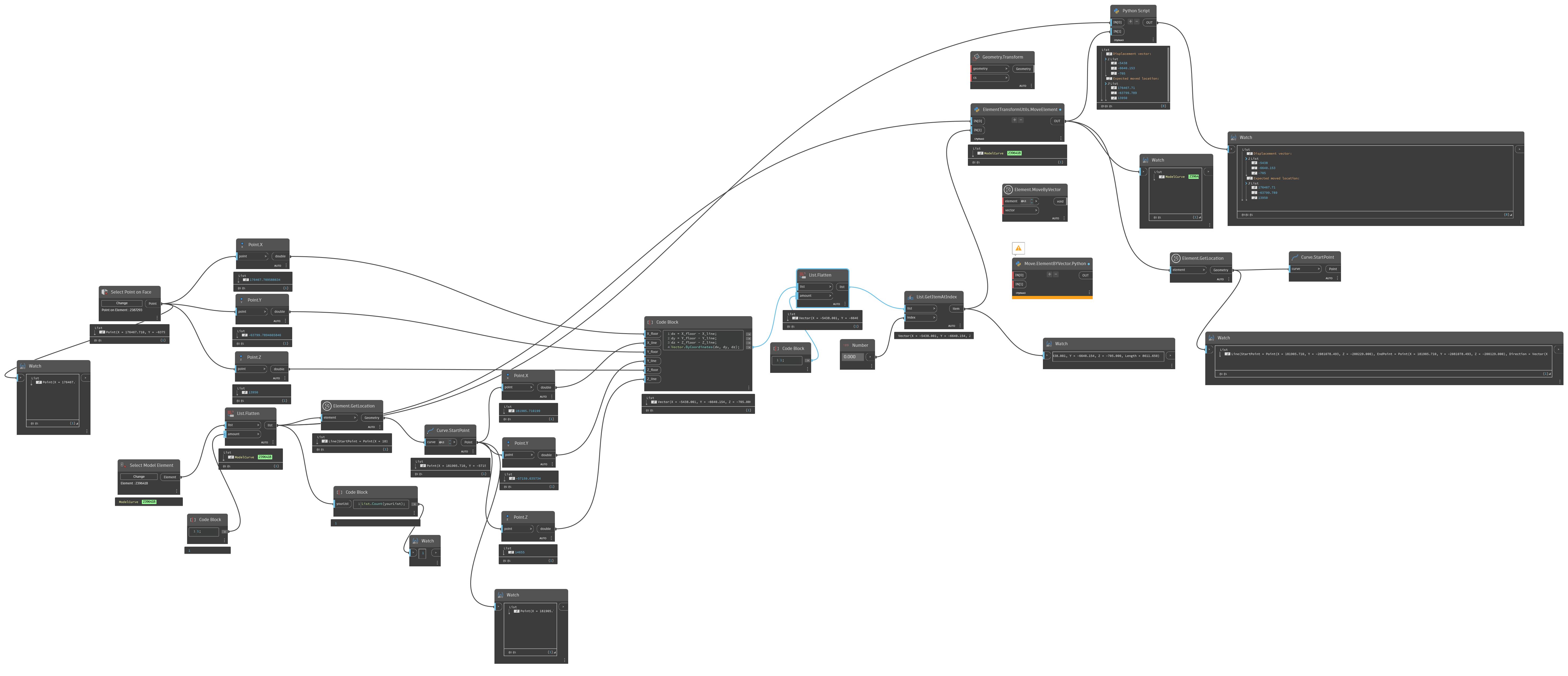
Please find dynamo graph attached
Edit: 15.08.2025
import clr
clr.AddReference('RevitAPI')
from Autodesk.Revit.DB import ElementTransformUtils, XYZ
clr.AddReference('RevitServices')
from RevitServices.Persistence import DocumentManager
from RevitServices.Transactions import TransactionManager
doc = DocumentManager.Instance.CurrentDBDocument
# Inputs
elements = IN[0]
vector_mm = IN[1]
# Convert to flat list
def flatten(input):
if isinstance(input, list):
result = []
for i in input:
result.extend(flatten(i))
return result
else:
return [input]
elements = flatten(elements)
elements = [UnwrapElement(e) for e in elements]
# Convert mm to feet
mm_to_ft = 1.0 / 304.8
try:
vector_ft = XYZ(
vector_mm.X * mm_to_ft,
vector_mm.Y * mm_to_ft,
vector_mm.Z * mm_to_ft
)
except:
vector_ft = vector_mm # fallback (if already XYZ in ft)
# Move elements
TransactionManager.Instance.EnsureInTransaction(doc)
moved = []
errors = []
for el in elements:
try:
ElementTransformUtils.MoveElement(doc, el.Id, vector_ft)
moved.append(el)
except Exception as e:
errors.append((el.Id, str(e)))
TransactionManager.Instance.TransactionTaskDone()
# Output
if errors:
OUT = ("Some elements failed to move", errors)
else:
OUT = ("All elements moved", moved)
I'm using Dynamo to move a Model Line (ModelCurve) in Revit via a displacement vector. The operation works correctly for the Y and Z directions, but fails silently for the X direction — the element does not move along X, and there is no error or warning.
After investigating, I’ve determined that this is due to the Model Line being associated with a Sketch Plane, which restricts its movement to the plane itself. Since ModelCurve.SketchPlane is a read-only property, it seems there is no way to detach the line or change its plane after creation.
Question:
Is there a way to detach or override the sketch plane of an existing Model Line so it becomes a free-floating element (i.e., can move in all directions)?
Thank you
Solved! Go to Solution.
.png)