- Home
- /
- Product Design & Manufacturing
- /
- Inventor Forums
- /
- Inventor Ideas
- /
- Tube and PIpe Overhaul
Turn on suggestions
Auto-suggest helps you quickly narrow down your search results by suggesting possible matches as you type.
 This page has been translated for your convenience with an automatic translation service. This is not an official translation and may contain errors and inaccurate translations. Autodesk does not warrant, either expressly or implied, the accuracy, reliability or completeness of the information translated by the machine translation service and will not be liable for damages or losses caused by the trust placed in the translation service.
Translate
This page has been translated for your convenience with an automatic translation service. This is not an official translation and may contain errors and inaccurate translations. Autodesk does not warrant, either expressly or implied, the accuracy, reliability or completeness of the information translated by the machine translation service and will not be liable for damages or losses caused by the trust placed in the translation service.
Translate
Options
- Subscribe to RSS Feed
- Mark as New
- Mark as Read
- Bookmark
- Subscribe
- Printer Friendly Page
- Report
Tube and PIpe Overhaul


Tube and PIpe Overhaul
I’ve been using Inventor for the past 11 years or so but only in the last 2 I’ve started using Tube and Pipe on daily bases. I’ve reviewed almost every tutorial, video, blog, existing on the matter but still find there are a lot of bugs, and room for improvement so during the course of one week while doing my daily job I’ve decided to add all the little things that got in the way of being more productive. It took another week to get the images and animations and to prepare the document but I am sure that even for non Tube and Pipe users this will make sense and cast a vote.
I am not sure if it was better to split all these ideas into separate posts or keep it as one. I think that some of the requests have been mentioned before so I apologise for that but I thought to keep it all together hopping to rather get a general overhaul of the Tube and Pipe environment so please vote for it even if they seem duplicate (add links to other posts so we can vote them there as well, please).
In no particular order here they are:
1 - If you don’t populate the route it can be really hard to place fittings. It doesn’t snap to nodes. Need to increase the snap influence area (or make the nodes bigger) so you can drop parts without populating the routes because this affects performance especially on large assemblies where we don’t populate until the very end. In the first part of the animation I am trying to place while in route only (or an unpopulated route) and it fails while with “populated” / ”display all objects” it’s really easy to drop fittings. Glyph and node custom size value needs implementing (nodes, arrows, etc), in T&P settings (template file) or even better in Inventor Settings customizable per user. I’ve seen a lot of requests from users of FEA and other modules as well for this.

2 - Possibility to increase the arrow sizes (glyph) when routing or rotating in T&P settings (template file) or even better in Inventor Settings customizable per user. I hold the mouse over the arrow direction while typing an angle and I constantly need to increase the size to make sure the mouse doesn’t run away and that it stays on the arrow.
3 - While in route you can’t delete multiple work features in Included Geometry, and you need to select and delete each one individually. This is very time consuming, and we need to be able to use delete on selected items.

4 - When inserting a node into a route the newly created segments should try and maintain (copy maybe) the original segment’s constraints and dimensions. We only need to dimension the position of the newly inserted node in regard to existing geometry. Fully constrained sketches go crazy when inserting a single node, removing existing constraints and deleting dimensions in the process as well.

5 - When placing fittings you get a rotation dialog but no “edit connection” or “change size” dialog. While in rotation mode an edit connection / change size should be available in the right click menu. You now need to start each command separately; you finish placing, select fitting, edit connection, select the fitting, change size, select fitting again, and so on in way too many steps. When you finish the Edit Connection /Change Size it should revert back to rotation mode dialog. I place similar fittings from adjacent runs because it’s easy but most of the time they are of different size and they need a different connecting dimension.

6 - Not all commands have shortcut keys or can be assigned keys to them. I don’t use the ribbon, and we all like the keyboard shortcut keys so please have them all available. Some things I will mention: edit fitting orientation, edit fitting connections, change fitting diameter, restore fitting, finish route (read bellow on why go to parent CTRL+ENTER is not working) etc. All these commands are only available from the right click menu or ribbon making it time consuming to use.

7 - Included geometry inside routes (planes, points) should have visibility off as soon as you exit the route. I haven’t found anyone that needs those visible once outside the route. You certainly don’t use them for “include geometry” in other routes. Turning the visibility from visibility menu / object visibility is not an option especially for large assemblies; we need proper off for each and every, not needing to manually change their state. I would not complain if you could turn multiple features off instead of one at a time as mentioned down bellow but even better turn them off automatically and let us turn them on if we want/need to once outside the routes.
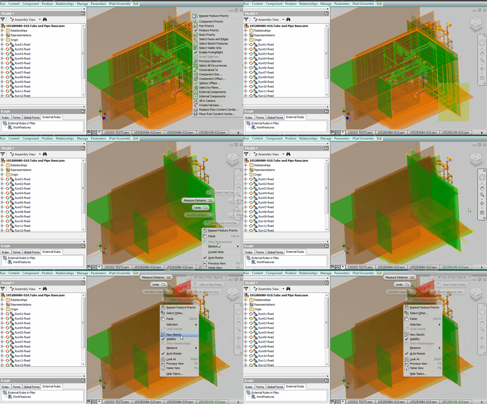
8 - Branches are an absolute must, tees or not. If the user doesn’t specifies a tee family in the style library (need to add a tee selection menu there) then pipes would intersect to simulate a welded connection. Notches in the larger pipe diameter should be added automatically if user settings “notch matching branches” in style selected, just like in the branch fitting author dialog. I’ve never used a cross (too expensive, company standard to avoid them) so I can’t advice on those but on tees if you have three lines with end points coincident, two of them collinear and third perpendicular (or 45 for Y) then that’s a tee connection. At least give us the option to connect them and manually place the tee, right now it complains about branches not being allowed, so you can’t connect nodes. My work around is to dimension nodes at a distance but the sketch is not fully constrained and the route segment can jump since more than one solution exists. This is how it needs to work:

9 - All routes need to be constrained and grounded at T&P origin to stop them from flying around. What’s the reason for not having it this way? Fittings inside the runs get connected around but the run itself never gets constrained, or moved around, individual routes are constrained by using include geometry. If needed the ground should be available to manually remove. Currently I am manually constraining the Tube and Pipe assembly and all the runs in it because if you move it by just a bit you’re pulling your hair wondering why it’s skewed.
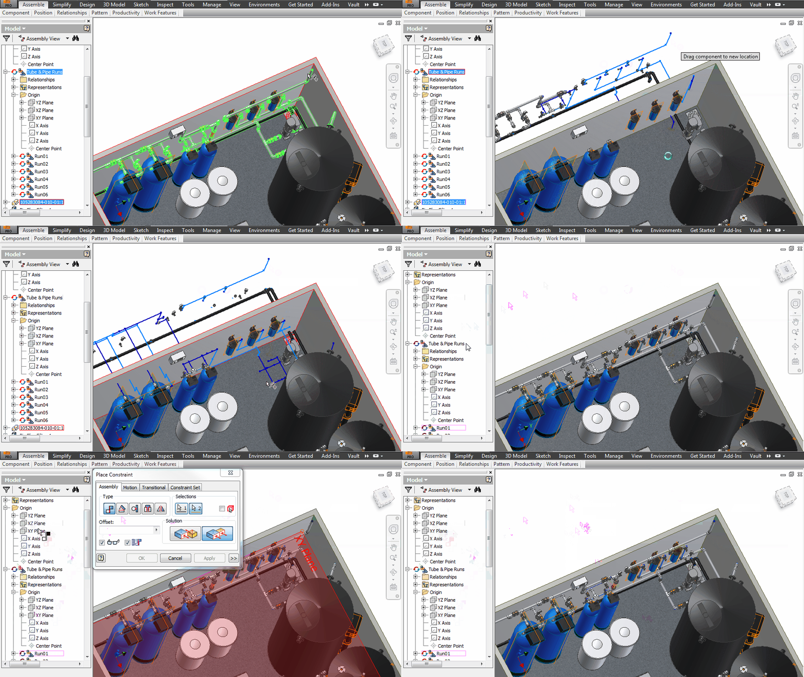
10 - When placing from content center the fittings default size selection should be the last used size, instead of defaulting to first item in the list every time. This way when you start placing fittings you only choose size first time, and the rest should follow. Different route? Different size? Then change size first placed item and the rest should follow again. I was going to suggest using the run size for each content center placed fitting but each run can have multiple routes each with its own size.

11 - Allow multiple T&P assemblies to exist and to be editable in the same assembly. Each assembly can have only one Tube and Pipe subassembly, editable at one time, if you need to edit an assembly with multiple skids or multiple layouts (more than one T&P) assembly you can't at the moment.

12 - When equipment moves (defer update, or changed outside main assembly) the routes go into “violation” mode where they turn pink, and all components of the route have visibility off. At this point the route is partially blocked for editing, you can delete constraints or segments but you can’t start a route in a different point or most important can’t insert nodes. I insert nodes to change direction, orientation and brake and fix routes but I need to do it before moving equipment predicting what might go wrong, or use undo, redo to bounce back and forward predicting how the change might affect the route. Deleting segments is not an option because the end points of the segments might hold fittings that get deleted in the process and need re-placing.

13 - T&P equipment should change size dynamically. Each Content Center fitting (pipe, elbows, tees, etc.) should get the size from the previously item populated. If I drop a reducer in the line the rest of the fittings and segments items should change automatically (Prompt the user if he wants to change, the rest of the elements along the route). The limitation here would be that it works with Content Center and iparts only, not individual authored fittings, because they don’t have a family table to feed from so they will not change as the rest (they can’t). This is how it needs to work:

14 - Stop routes from jumping while dragging nodes. The only way to check if a route is fully constrained and movable segments is to drag random nodes and see if they are moving. Sometimes more than one solution error occurs when the route jumps on either side of a dimension. Use negative/positive dimensions like with planes, or positive along origin indicators and negative in opposite direction, or lock the dimension in place and allow a flip option on a right click contextual menu. Sometimes a route is fully constrained but because of more than one solution on these dimensions it doesn’t report or change colour to fully constrained, or even worse, when changing dimensions you end up with overlapping and intersecting segments which goes into “Route Violation”.

15 - Pressing the “Return” or “Return to Parent” (CTRL+ENTER or CTRL+=) button will not exit the route environment, it will send you to 3D Sketch forcing you to press “CTRL+ENTER” again to exit route into run environment. Key shortcut for Finish Route is needed we don’t like to hunt for buttons on hidden menus ( I keep mine as Minimize to Tabs to increase display area). Sometimes when exiting the environment by using CTRL+ENTER twice doesn’t restore the visibility of the route components to on, so you need to select them all and turn them visible or edit the route and exit with the “finish route” button on the ribbon.

16 - Multiple selection working commands. We need to be able to run regular commands on a selection set because right now you need to select each and every component to do stuff like: change size, edit fitting connection (to increase gap distance), make adaptive, etc.
17 - Content Center pipes need re-authoring and ipart template should be set to “Participate in Assembly and Drawing Sections”. I’ve never wanted a pipe to run outside the section view but if I do I can turn off section participant for those ones. This needs to come in Inventor as default, not needing to republish standard CC libraries.
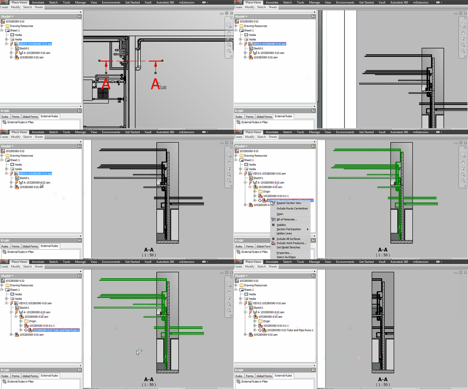
18 - Tube and Pipe Content Center items don’t get the properties specified in the Content Center family template. I get no part number and no description all the time. Make it work like steel shapes, I am not getting Description or Part number from Content Center Pipes and Spools.

19 - Include Route Centrelines in the drawing should show centreline for visible items only (use browser view to check which ones are visible). It’s showing for the whole Runs ending up with a lot of lines for which you need to turn visibility off, one by one.
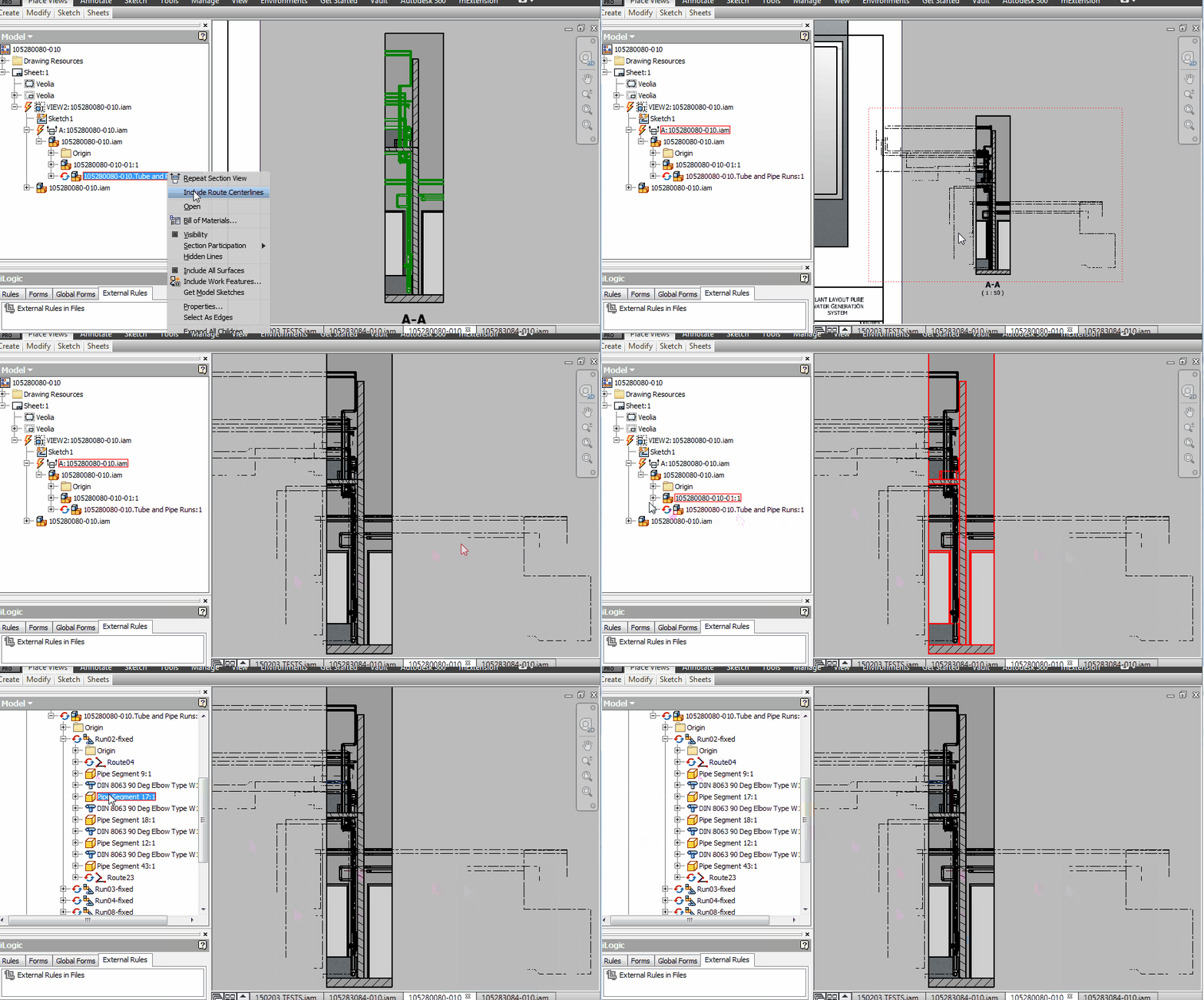
20 - Manually changed pipes and fittings should stay that size when Style Size changes, because this changes everything including your manual changed elements. If you decide to change style (size of the routes) then a warning should pup-up asking for confirmation: “Sizes of some elements were manually changed. Do you want to update all? YES/NO/CANCEL”
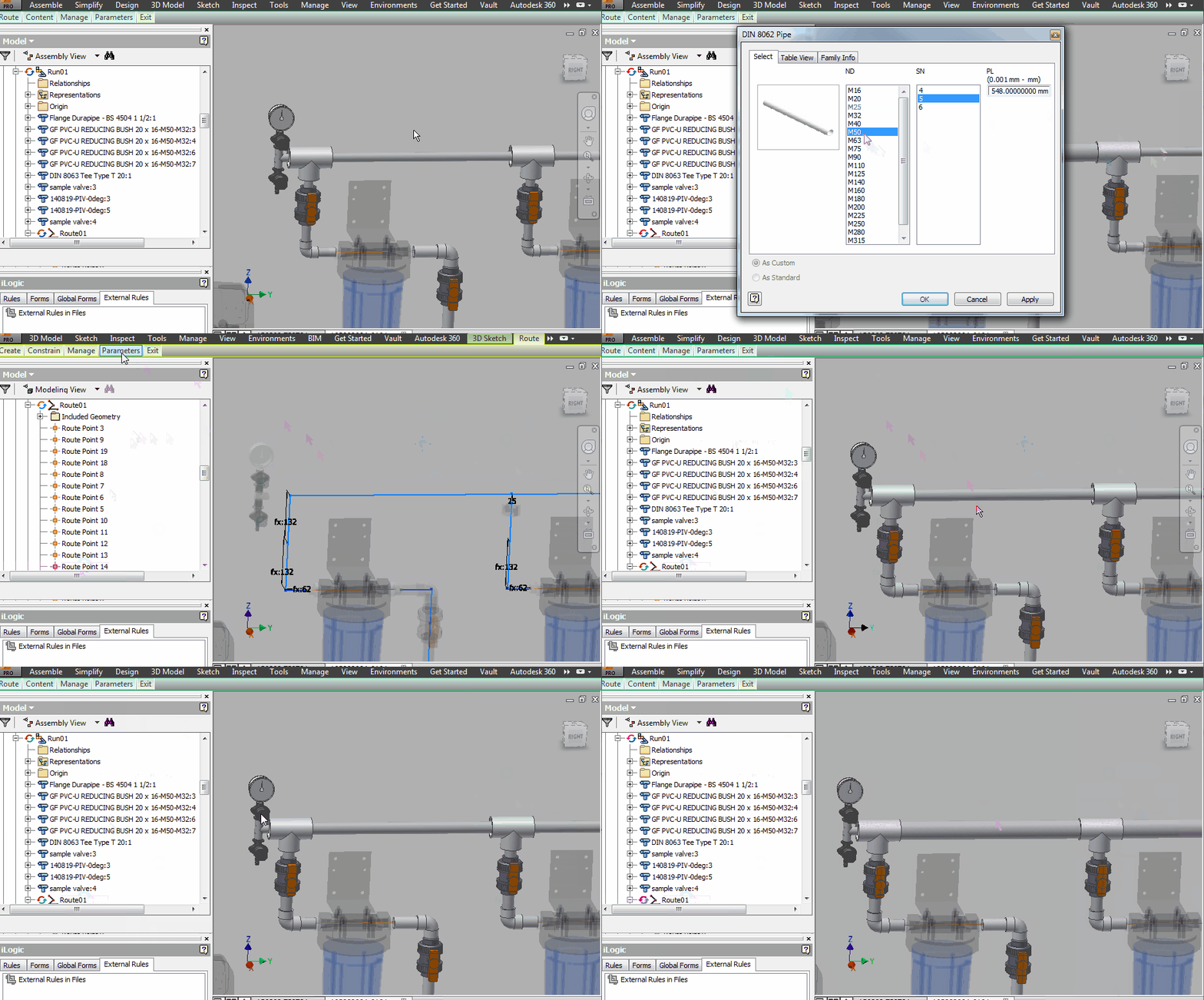
21 - Changing size of multiple CC items has been approved, see here: http://forums.autodesk.com/t5/inventor-ideastation/tube-and-pipe-multiple-selection-change-size/idi-.... We need same ability for Pipes; if you select multiple pipes (in fact multiple items altogether, fittings and pipes) you should be able to use change size to modify them all as long as the families have same values for ND (or whatever they main key parameter is). If the only way of programming this into Inventor is by having same name for the key parameter on all T&P families (ND or whatever Autodesk decides) then I am ready to modify all my custom families in order to get this functionality going.

22 - Last used Content Center family in Change Size should be cached in memory; it takes forever for the family size menu to show up again even if you just used it.

23 - Can’t dynamically dimension using parameter names. When entering dimensions for route segments you can only type numerical value to start the dimension dialog, then you need to delete the value and you can type a parameter name but the dimension is changed back to a fixed value instead of being “parameter=dimension”. It seems to copy the value of the parameter like “d22=30mm” instead assigning the parameter to the dimension like “d22=vb”. I import parameters from xml for each style/size so while dimensioning I use items like “vb” (valve ball), or gp (gap), or “e” (tee and elbow) to dimension distance between nodes based on what goes into that node ,ball valve, tee, elbow, etc.

24 - Constraints are not always visible for nodes. In the next image the node is coincident with the blue segment (extension of “fx:132”), and I can’t remove this constraint. ON/OFF switching of show constraints doesn’t fix it. Notice that 3D/Move Rotate is missing in the contextual menu because of the constraint being present but I can’t select it and delete it.
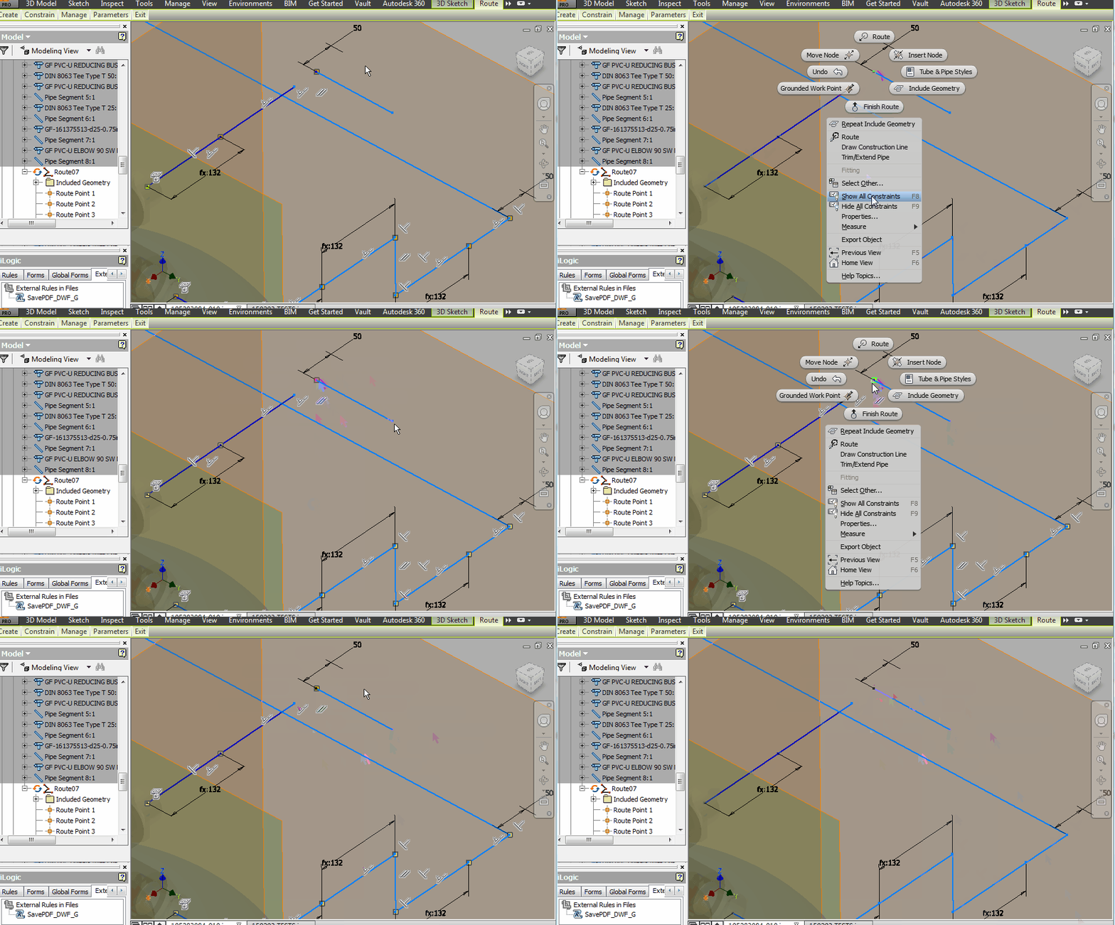
25 - Need to be able to change orientation plane for multiple dimensions while in isometric view. Right now you dimension, right click, Annotation Plane, Show All Part Work Planes, choose a different plane, click to place dimension (“spacebar” is not always working, see below). We need to be able to select multiple dimensions, and change orientation plane for all at same time.

26 - Need to be able to do Chain Dimension for isometric views with option for Annotation Plane. Right now we need to manually dimension each route segment and choose annotation (“spacebar not always working, see below) plane which is very time-consuming.

27 - Make “SPACEBAR” work all the time for quick changing annotation plane while dimensioning Isometric drawings. Next I am showing how it’s meant to work and that sometimes it’s not and you need to manually specify work plane annotation. It’s not always working while selecting segments; you need to play with selecting segment end points.

28 - Exit without saving still saves changes. If you use change size on pipes and then you close without saving it still saves the file, even if you shut down inventor to clear its cache memory and start a new session, the changes are persistent.

29 - Decrease the length of the generated files and folders for any design accelerator, tube and pipe, frame generator, FEA items. It’s so easy to pass the 256 accepted characters in Microsoft Windows and you end up with all sort of problems, like unable to access and recover parts.
The next one I can’t reproduce, I've been having it but I can’t seem to be able to get it again, so if anyone has seen this and has a case at hand please add it in the comments bellow.
30 - While moving equipment around some routes go into “Violation” mode and the only option is to CANCEL the command which will undo your work, and to edit the route braking constraints or deleting dimensions first. This is somehow related and really a continuation of the first one, so even if the route goes into “violation” the operation should be permitted to finalize and let the user change the route manually later in order to fix it.
91 Comments
Forums Links
Can't find what you're looking for? Ask the community or share your knowledge.