Community
Inventor Forum
Welcome to Autodesk’s Inventor Forums. Share your knowledge, ask questions, and explore popular Inventor topics.
Turn on suggestions
Auto-suggest helps you quickly narrow down your search results by suggesting possible matches as you type.
Reply
Topic Options
- Subscribe to RSS Feed
- Mark Topic as New
- Mark Topic as Read
- Float this Topic for Current User
- Bookmark
- Subscribe
- Printer Friendly Page
- « Previous
- Next »
Message 1 of 64
03-30-2010
06:59 AM
- Mark as New
- Bookmark
- Subscribe
- Mute
- Subscribe to RSS Feed
- Permalink
- Report
03-30-2010
06:59 AM
Double curved Reinforcemnt ring Challenge!
Hello,
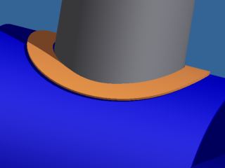
I need to mode a reinforcement ring for a pressure vessel. The ring needs to have a round hole in the middle for the pipe insert. The width of the ring needs to be constant. In the drawing it is the orange part. How can I model this ring?
I need to mode a reinforcement ring for a pressure vessel. The ring needs to have a round hole in the middle for the pipe insert. The width of the ring needs to be constant. In the drawing it is the orange part. How can I model this ring?
63 REPLIES 63
Message 61 of 64
07-10-2024
10:13 PM
- Mark as New
- Bookmark
- Subscribe
- Mute
- Subscribe to RSS Feed
- Permalink
- Report
07-10-2024
10:13 PM
I was under impression - that particular design had been sorted out years ago,
Apparently - not. Or the OP just didn't look up the archives.
Cheers,
Igor.
Web: www.meqc.com.au
Message 62 of 64
07-11-2024
11:56 AM
- Mark as New
- Bookmark
- Subscribe
- Mute
- Subscribe to RSS Feed
- Permalink
- Report
07-11-2024
11:56 AM
The hole in a repad, theoretically the intersection of two perpendicular cylinders, is not an ellipse. An ellipse will get you close enough for any reasonable manufacturing process, but this topic has concentrated on theoretically perfect, not just close enough.
An ellipse is the geometric intersection of a plane and a cylinder. If the plane is perpendicular to the cylinder, the result is a circle, which is a special case of an ellipse. I created a geometrically (nearly) perfect repad, created a flat pattern and a drawing of it. Below is a Flat Pattern view with measurements at various angles of the section width, and an ellipse sketched at the center in red. As you can see, it does not match the center opening exactly. This is reasonable, since a circle through a cylinder, flattened, is not geometrically an ellipse.

I've attached my (nearly) perfect repad model (Inventor 2025 format), but I note that this is more work than it is worth, given manufacturing tolerances. Does the ASME code specify how consistent the repad ring width must be? Everything in fabrication has a tolerance, just as everything in modeling does. Typically, we would like for modeling tolerances to be orders of magnitude tighter than manufacturing tolerances, as they routinely are.
For those on previous versions, this is the model process I used:
- Trim a circle through a cylindrical surface
- Thicken the resulting surface to a solid (sheet metal) body
- Unfold the part
- Offset the hole profile by the required ring width
- Trim off the outer parts (Extrude/Intersection) except for a small remnant to allow refolding
- Refold the part
- Delete Face w/Heal the remnant noted above

But still-- how close do codes require us to be to perfectly uniform width?
Sam B
Inventor Pro 2025.0.1 | Windows 11 Home 23H2

Message 63 of 64
07-11-2024
02:44 PM
- Mark as New
- Bookmark
- Subscribe
- Mute
- Subscribe to RSS Feed
- Permalink
- Report
07-11-2024
02:44 PM
what you have is more precise than required. yes, this is way more work than it should be.
Message 64 of 64
07-11-2024
05:03 PM
- Mark as New
- Bookmark
- Subscribe
- Mute
- Subscribe to RSS Feed
- Permalink
- Report
07-11-2024
05:03 PM
This version is even more perfect (consistent width to 7 decimal places) and simpler to produce. I guess if you're doing this every day, you would want a dedicated tool to do the job, but for occasional use this is pretty reasonable in my estimation. Inventor 2025 format.

With two-way symmetry I decided it is easier to model a quarter of it and mirror twice; also makes Unfold/Refold simpler.
Sam B
Inventor Pro 2025.0.1 | Windows 11 Home 23H2
- « Previous
- Next »
Reply
Topic Options
- Subscribe to RSS Feed
- Mark Topic as New
- Mark Topic as Read
- Float this Topic for Current User
- Bookmark
- Subscribe
- Printer Friendly Page
- « Previous
- Next »
Forums Links
Can't find what you're looking for? Ask the community or share your knowledge.
Post to forums
