Community
Inventor Forum
Welcome to Autodesk’s Inventor Forums. Share your knowledge, ask questions, and explore popular Inventor topics.
Turn on suggestions
Auto-suggest helps you quickly narrow down your search results by suggesting possible matches as you type.
Reply
Topic Options
- Subscribe to RSS Feed
- Mark Topic as New
- Mark Topic as Read
- Float this Topic for Current User
- Bookmark
- Subscribe
- Printer Friendly Page
Message 1 of 64
03-30-2010
06:59 AM
- Mark as New
- Bookmark
- Subscribe
- Mute
- Subscribe to RSS Feed
- Permalink
- Report
03-30-2010
06:59 AM
Double curved Reinforcemnt ring Challenge!
Hello,
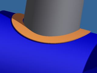
I need to mode a reinforcement ring for a pressure vessel. The ring needs to have a round hole in the middle for the pipe insert. The width of the ring needs to be constant. In the drawing it is the orange part. How can I model this ring?
I need to mode a reinforcement ring for a pressure vessel. The ring needs to have a round hole in the middle for the pipe insert. The width of the ring needs to be constant. In the drawing it is the orange part. How can I model this ring?
63 REPLIES 63
Message 2 of 64
03-30-2010
07:48 AM
- Mark as New
- Bookmark
- Subscribe
- Mute
- Subscribe to RSS Feed
- Permalink
- Report
03-30-2010
07:48 AM
2010
Someone else might have a better way.
(On as small a scale as I used I guess it doesn't look so good.)
Someone else might have a better way.
(On as small a scale as I used I guess it doesn't look so good.)
Message 3 of 64
03-30-2010
07:51 AM
- Mark as New
- Bookmark
- Subscribe
- Mute
- Subscribe to RSS Feed
- Permalink
- Report
03-30-2010
07:51 AM
I think I have an idea for the constant width, I'll have to get back to you.
Message 4 of 64
03-30-2010
07:58 AM
- Mark as New
- Bookmark
- Subscribe
- Mute
- Subscribe to RSS Feed
- Permalink
- Report
03-30-2010
07:58 AM
I don't understand why it can't be converted to sheet metal (I'm assuming what you really need is a flat pattern), I'll have to look into it if I get a chance.
Message 5 of 64
03-30-2010
08:09 AM
- Mark as New
- Bookmark
- Subscribe
- Mute
- Subscribe to RSS Feed
- Permalink
- Report
03-30-2010
08:09 AM
In addition to Dan's suggestion here are 2 more methods, that may or may not work for you.
one uses the Bend Part tool
the other uses a 3d sketch to project to a surface, then Split, then Thicken
one uses the Bend Part tool
the other uses a 3d sketch to project to a surface, then Split, then Thicken
Message 6 of 64
03-30-2010
08:13 AM
- Mark as New
- Bookmark
- Subscribe
- Mute
- Subscribe to RSS Feed
- Permalink
- Report
03-30-2010
08:13 AM
It is no problem for me to convert it to sheet metal. I need to make a flat-pattern so that the lasercutter can make my model. And then bend it around the vessel. The constant width is a requirement. The edges of the inner hole for the pipe needs to be prepared afterwards for welding. I'm now not at my Inventor pc so I can't check out your solutions right now. I will look at them tomorrow.
At least many thanks for your effort.
At least many thanks for your effort.
Message 7 of 64
03-30-2010
08:22 AM
- Mark as New
- Bookmark
- Subscribe
- Mute
- Subscribe to RSS Feed
- Permalink
- Report
03-30-2010
08:22 AM
Project two concentric circles to the horz cylinder and then split the
surface twice. Thicken the resulting surface.
--
Sean Dotson, PE
www.mcadforums.com
www.ipropwiz.com
"hardsniffer" wrote in message news:6363379@discussion.autodesk.com...
> Hello,
>
> I need to mode a reinforcement ring for a pressure vessel. The ring needs
> to have a round hole in the middle for the pipe insert. The width of the
> ring needs to be constant. In the drawing it is the orange part. How can I
> model this ring?
>
Message 8 of 64
03-30-2010
08:23 AM
- Mark as New
- Bookmark
- Subscribe
- Mute
- Subscribe to RSS Feed
- Permalink
- Report
03-30-2010
08:23 AM
Ah I see Bmiller has given you an illustration of what I meant.
--
Sean Dotson, PE
www.mcadforums.com
www.ipropwiz.com
"Sean Dotson" wrote in message
news:6363503@discussion.autodesk.com...
> Project two concentric circles to the horz cylinder and then split the
> surface twice. Thicken the resulting surface.
>
> --
> Sean Dotson, PE
> www.mcadforums.com
> www.ipropwiz.com
>
> "hardsniffer" wrote in message news:6363379@discussion.autodesk.com...
>> Hello,
>>
>> I need to mode a reinforcement ring for a pressure vessel. The ring needs
>> to have a round hole in the middle for the pipe insert. The width of the
>> ring needs to be constant. In the drawing it is the orange part. How can
>> I
>> model this ring?
>>
--
Sean Dotson, PE
www.mcadforums.com
www.ipropwiz.com
"Sean Dotson"
news:6363503@discussion.autodesk.com...
> Project two concentric circles to the horz cylinder and then split the
> surface twice. Thicken the resulting surface.
>
> --
> Sean Dotson, PE
> www.mcadforums.com
> www.ipropwiz.com
>
> "hardsniffer" wrote in message news:6363379@discussion.autodesk.com...
>> Hello,
>>
>> I need to mode a reinforcement ring for a pressure vessel. The ring needs
>> to have a round hole in the middle for the pipe insert. The width of the
>> ring needs to be constant. In the drawing it is the orange part. How can
>> I
>> model this ring?
>>
Message 9 of 64
03-30-2010
08:33 AM
- Mark as New
- Bookmark
- Subscribe
- Mute
- Subscribe to RSS Feed
- Permalink
- Report
03-30-2010
08:33 AM
The problem is the width isn't constant. You can see that in my first example, as the pipes get bigger it will be less noticeable but it's still there.
I did that for the "center cutout" exported to dxf, made a new part and offset the dxf curve then folded it. I think that's about as close as I can get.
I did that for the "center cutout" exported to dxf, made a new part and offset the dxf curve then folded it. I think that's about as close as I can get.
Message 10 of 64
03-30-2010
08:47 AM
- Mark as New
- Bookmark
- Subscribe
- Mute
- Subscribe to RSS Feed
- Permalink
- Report
03-30-2010
08:47 AM
There are a number of ways to model a repad in Inventor. Attached is a
quick version of one of my favorites. It's set up to be nearly constant
width, probably close enough for most applications. With a bit of algebra
it could be easily made true. This one is set up with named parameters so it
makes a good template. It constrains easily to the assembly on origin
centerlines, and has a usable flat pattern.
Cheers,
Walt
Message 11 of 64
03-30-2010
08:49 AM
- Mark as New
- Bookmark
- Subscribe
- Mute
- Subscribe to RSS Feed
- Permalink
- Report
03-30-2010
08:49 AM
The first saddle.ipt used two separate surfaces to trim a third instead of projecting curves to surface and split but the result is exactly the same - and does not satisfy the equal width requirement.
If I had to guess, I'd think the OP didn't want to limit the responses by listing all the methods that had been tried, maybe hoping that it was just something simple that had been missed.
If I had to guess, I'd think the OP didn't want to limit the responses by listing all the methods that had been tried, maybe hoping that it was just something simple that had been missed.
Message 12 of 64
03-30-2010
08:50 AM
- Mark as New
- Bookmark
- Subscribe
- Mute
- Subscribe to RSS Feed
- Permalink
- Report
03-30-2010
08:50 AM
When you project two circles to the cylindrical face, the inner circle is not round anymore and then the width is not constant. The problem of bending is the deformation in the solid.
Message 13 of 64
03-30-2010
08:55 AM
- Mark as New
- Bookmark
- Subscribe
- Mute
- Subscribe to RSS Feed
- Permalink
- Report
03-30-2010
08:55 AM
> When you project two circles to the cylindrical face, the inner circle is not round anymore and then the width is not constant.
using a 3d sketch and the option to wrap to surface, it should be
using a 3d sketch and the option to wrap to surface, it should be
Message 14 of 64
03-30-2010
08:56 AM
- Mark as New
- Bookmark
- Subscribe
- Mute
- Subscribe to RSS Feed
- Permalink
- Report
03-30-2010
08:56 AM
as a quick thought, possibly overkill...
extude a flat square patch
fold to large pipe OD
cut the smaller pipe's intersection
unfold
offset the hole to provide a constant thickness, extrude as intersect
refold back
as i said, probably complete overkill (and still not what you want)...
just a thought, Sam
wrote in message news:6363584@discussion.autodesk.com...
When you project two circles to the cylindrical face, the inner circle is
not round anymore and then the width is not constant. The problem of bending
is the deformation in the solid.
extude a flat square patch
fold to large pipe OD
cut the smaller pipe's intersection
unfold
offset the hole to provide a constant thickness, extrude as intersect
refold back
as i said, probably complete overkill (and still not what you want)...
just a thought, Sam
When you project two circles to the cylindrical face, the inner circle is
not round anymore and then the width is not constant. The problem of bending
is the deformation in the solid.
Message 15 of 64
03-30-2010
08:57 AM
- Mark as New
- Bookmark
- Subscribe
- Mute
- Subscribe to RSS Feed
- Permalink
- Report
03-30-2010
08:57 AM
"This model cannot be converted to Sheet Metal because it contains features that have created multiple bodies. In order to convert to Sheet Metal these features must first be removed"
Anybody know what that means?
Anybody know what that means?
Message 16 of 64
03-30-2010
09:19 AM
- Mark as New
- Bookmark
- Subscribe
- Mute
- Subscribe to RSS Feed
- Permalink
- Report
03-30-2010
09:19 AM
The smaller pipe has to go through the hole, so the inner "circle" isn't round, the outer one has to be "equidistant"
I tried with the plug and just made a sketch on the flat pattern with an offset for the "O.D." then copied that sketch to a new part to extrude and fold.
(Plus I remembered you can split to a sketch so all you need is the surface of the larger pipe and the sketch of the smaller, no need to project.)
Message 17 of 64
03-30-2010
09:26 AM
- Mark as New
- Bookmark
- Subscribe
- Mute
- Subscribe to RSS Feed
- Permalink
- Report
03-30-2010
09:26 AM
No time to give all the variations, but here's one example in 2010. Just
finish off the Collar as you see fit. Replay the model tree in the
collar part.
--
Dennis Jeffrey, Autodesk Inventor Certified Expert
Subscribe to the free "The Creative Inventor Magazine now available at:
http://teknigroup.com/CI-Subscribe-Login.asp
finish off the Collar as you see fit. Replay the model tree in the
collar part.
--
Dennis Jeffrey, Autodesk Inventor Certified Expert
Subscribe to the free "The Creative Inventor Magazine now available at:
http://teknigroup.com/CI-Subscribe-Login.asp
Message 18 of 64
03-30-2010
09:26 AM
- Mark as New
- Bookmark
- Subscribe
- Mute
- Subscribe to RSS Feed
- Permalink
- Report
03-30-2010
09:26 AM
ah, I got ya, I was reading that to mean the inverse of what he meant.
I see what you're saying concering the inner hole as well.
I'd just project normally (or by vector in the 3d sketch and get the shape needed.
Then clean up the flat with an extrude to remove any belveled edges.
I see what you're saying concering the inner hole as well.
I'd just project normally (or by vector in the 3d sketch and get the shape needed.
Then clean up the flat with an extrude to remove any belveled edges.
Message 19 of 64
03-31-2010
10:22 AM
- Mark as New
- Bookmark
- Subscribe
- Mute
- Subscribe to RSS Feed
- Permalink
- Report
03-31-2010
10:22 AM
"The width of the ring needs to be constant."
I missed it the first time too.
It's pretty amazing the number of subtle different ways to get the same result - surfaces vs. sketches, split vs. delete face, etc. - too bad we still haven't come up with a decent way to meet that one requirement: "The width of the ring needs to be constant."
I missed it the first time too.
It's pretty amazing the number of subtle different ways to get the same result - surfaces vs. sketches, split vs. delete face, etc. - too bad we still haven't come up with a decent way to meet that one requirement: "The width of the ring needs to be constant."
Message 20 of 64
03-31-2010
10:27 AM
- Mark as New
- Bookmark
- Subscribe
- Mute
- Subscribe to RSS Feed
- Permalink
- Report
03-31-2010
10:27 AM
>too bad we still haven't come up with a decent way to meet that one requirement: "The width of the ring needs >to be constant."
wouldn't any of the options that provide a flat pattern have a constant width?
I think projecting the center hole stright down and the "re-cutting" it in the flat is the way to go to clean up the bevels, no?
wouldn't any of the options that provide a flat pattern have a constant width?
I think projecting the center hole stright down and the "re-cutting" it in the flat is the way to go to clean up the bevels, no?
Reply
Topic Options
- Subscribe to RSS Feed
- Mark Topic as New
- Mark Topic as Read
- Float this Topic for Current User
- Bookmark
- Subscribe
- Printer Friendly Page
Forums Links
Can't find what you're looking for? Ask the community or share your knowledge.
Post to forums
