Community
Inventor Forum
Welcome to Autodesk’s Inventor Forums. Share your knowledge, ask questions, and explore popular Inventor topics.
Turn on suggestions
Auto-suggest helps you quickly narrow down your search results by suggesting possible matches as you type.
Reply
Topic Options
- Subscribe to RSS Feed
- Mark Topic as New
- Mark Topic as Read
- Float this Topic for Current User
- Bookmark
- Subscribe
- Printer Friendly Page
Message 1 of 64
03-30-2010
06:59 AM
- Mark as New
- Bookmark
- Subscribe
- Mute
- Subscribe to RSS Feed
- Permalink
- Report
03-30-2010
06:59 AM
Double curved Reinforcemnt ring Challenge!
Hello,
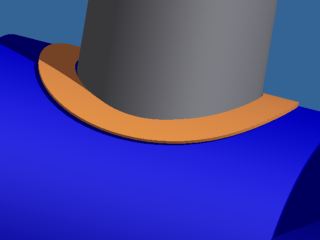
I need to mode a reinforcement ring for a pressure vessel. The ring needs to have a round hole in the middle for the pipe insert. The width of the ring needs to be constant. In the drawing it is the orange part. How can I model this ring?
I need to mode a reinforcement ring for a pressure vessel. The ring needs to have a round hole in the middle for the pipe insert. The width of the ring needs to be constant. In the drawing it is the orange part. How can I model this ring?
63 REPLIES 63
Message 41 of 64
04-01-2010
06:04 AM
- Mark as New
- Bookmark
- Subscribe
- Mute
- Subscribe to RSS Feed
- Permalink
- Report
04-01-2010
06:04 AM
For those that don't normally build vessels, here's the deal on the constant-width thing: the code looks at the amount of material that was cut out of the nozzle penetration, and then says you have to replace it, but it has to be within a certain distance of the cut - sorry, diagonals don't count.
Attached image shows what happens when the 'cylinder-cut' approach is used. Flat pattern is not constand width (see dimensions). Also, as many have pointed out, the outside edge will be normal to the vessel wall (cut flat, then rolled) but ideally the inside edge should be parallel to the nozzle wall (typically prepped after rolling).
AFAIK, there's no way to get this to BOTH model and flat-pattern correctly. Inventor uses either the inner or outer FACE to develop the flat pattern, so it doesn't understand a hole that's not normal to the sheet. The method I posted above gets the model right, but the FP is approximate.
Todd
Product Design Collection (Inventor Pro, 3DSMax, HSMWorks)
Fusion 360 / Fusion Team
Message 42 of 64
04-01-2010
06:24 AM
- Mark as New
- Bookmark
- Subscribe
- Mute
- Subscribe to RSS Feed
- Permalink
- Report
Message 43 of 64
04-01-2010
08:33 AM
- Mark as New
- Bookmark
- Subscribe
- Mute
- Subscribe to RSS Feed
- Permalink
- Report
04-01-2010
08:33 AM
[The kind of attitude that follows is why no one ever reads what I post.]
Kind of like what I finally came up with for saddle2xxx after saddle2 couldn't be converted to sheet metal to unfold.
But it's nice to have someone who works in the field that the problem comes from "reexamine the requirement to see exactly what we can get away with" like I was saying.
I thought I was crazy but there were a couple of variations to what I posted at quarter to eleven on Tuesday but also a couple of people came up with exactly the same solution (and rather than bother to read the posts shortly after that which explained why that wasn't right said "What's wrong with this?")
Message 44 of 64
04-01-2010
08:58 AM
- Mark as New
- Bookmark
- Subscribe
- Mute
- Subscribe to RSS Feed
- Permalink
- Report
04-01-2010
08:58 AM
The offset surface is a really neat idea. I just tried to duplicate your method but it gives me that "multiple bodies" error I was having problems with before, I'll have to go through your model more carefully to see where my problem is.
How come you and ToddHarris7556 wind up with three segments around the O.D.? When I finally got something to work there is only one seam on that face. Why there are any at all is confusing enough, why are some different?
How come you and ToddHarris7556 wind up with three segments around the O.D.? When I finally got something to work there is only one seam on that face. Why there are any at all is confusing enough, why are some different?
Message 45 of 64
04-01-2010
09:00 AM
- Mark as New
- Bookmark
- Subscribe
- Mute
- Subscribe to RSS Feed
- Permalink
- Report
04-01-2010
09:00 AM
The example I posted compensates for the curvature of the shell by making
the outer profile of the repad an elipse and controlling the vertical and
horizontal dimensions separately. It makes the horizontal width of the
repad a straight, aligned dimension (highlighted)--IOW it doesn't take the
final step and control the horizontal dimensions according to the arc-length
of the formed repad. Even with this, the horizontal and vertical repad
width come within 0.5mm for a 200mm OD pad.
The flat pattern and the formed model both agree, since the thicken method
of forming the solid extrudes normal to the face. This accurately mimics
the way the metal will deform when it's rolled. The flat pattern which is
where the features will be cut, shows the profile perfectly straight, and
plots both the inner and outer "circles" as spline curves, since neither is
perfectly circular.
Cheers,
Walt
Message 46 of 64
04-01-2010
09:26 PM
- Mark as New
- Bookmark
- Subscribe
- Mute
- Subscribe to RSS Feed
- Permalink
- Report
04-01-2010
09:26 PM
Hi Walt,
Using the same approach you have, I got the width of the pad spot on at all
four points. I have posted the file if you want to have a look at it.
Best Regards,
Igor.
--
Web: www.meqc.com.au
www.boatworks.meqc.com.au
"Walt Jaquith" wrote in message
news:6365453@discussion.autodesk.com...
The example I posted compensates for the curvature of the shell by making
the outer profile of the repad an elipse and controlling the vertical and
horizontal dimensions separately. It makes the horizontal width of the
repad a straight, aligned dimension (highlighted)--IOW it doesn't take the
final step and control the horizontal dimensions according to the arc-length
of the formed repad. Even with this, the horizontal and vertical repad
width come within 0.5mm for a 200mm OD pad.
The flat pattern and the formed model both agree, since the thicken method
of forming the solid extrudes normal to the face. This accurately mimics
the way the metal will deform when it's rolled. The flat pattern which is
where the features will be cut, shows the profile perfectly straight, and
plots both the inner and outer "circles" as spline curves, since neither is
perfectly circular.
Cheers,
Walt
Using the same approach you have, I got the width of the pad spot on at all
four points. I have posted the file if you want to have a look at it.
Best Regards,
Igor.
--
Web: www.meqc.com.au
www.boatworks.meqc.com.au
"Walt Jaquith"
news:6365453@discussion.autodesk.com...
The example I posted compensates for the curvature of the shell by making
the outer profile of the repad an elipse and controlling the vertical and
horizontal dimensions separately. It makes the horizontal width of the
repad a straight, aligned dimension (highlighted)--IOW it doesn't take the
final step and control the horizontal dimensions according to the arc-length
of the formed repad. Even with this, the horizontal and vertical repad
width come within 0.5mm for a 200mm OD pad.
The flat pattern and the formed model both agree, since the thicken method
of forming the solid extrudes normal to the face. This accurately mimics
the way the metal will deform when it's rolled. The flat pattern which is
where the features will be cut, shows the profile perfectly straight, and
plots both the inner and outer "circles" as spline curves, since neither is
perfectly circular.
Cheers,
Walt
Message 47 of 64
04-01-2010
09:26 PM
- Mark as New
- Bookmark
- Subscribe
- Mute
- Subscribe to RSS Feed
- Permalink
- Report
04-01-2010
09:26 PM
Since the object of the exercise was to get a repad of uniform width at all
four points - here it is. The width of the Collar is100mm sharp.
Attached is although an assembly file to see how the repad interacts with
the pipe. The Split2 in Collar.ipt is to accommodate the measuring across
the width when in Flat pattern. It can be either suppressed or deleted all
together.
The Flat pattern doesn't require any additional work as some other
contributors to this topic has suggested.
Best Regards,
Igor.
--
Web: www.meqc.com.au
www.boatworks.meqc.com.au
wrote in message news:6365157@discussion.autodesk.com...
To clear up some misunderstandings I give an example of the size:
Outerdiameter vessel: 1024mm
Outer diameter pipe: 518mm
Thickness repad: 10mm
Width repad: 100mm
four points - here it is. The width of the Collar is100mm sharp.
Attached is although an assembly file to see how the repad interacts with
the pipe. The Split2 in Collar.ipt is to accommodate the measuring across
the width when in Flat pattern. It can be either suppressed or deleted all
together.
The Flat pattern doesn't require any additional work as some other
contributors to this topic has suggested.
Best Regards,
Igor.
--
Web: www.meqc.com.au
www.boatworks.meqc.com.au
To clear up some misunderstandings I give an example of the size:
Outerdiameter vessel: 1024mm
Outer diameter pipe: 518mm
Thickness repad: 10mm
Width repad: 100mm
Message 48 of 64
04-02-2010
08:08 PM
- Mark as New
- Bookmark
- Subscribe
- Mute
- Subscribe to RSS Feed
- Permalink
- Report
04-02-2010
08:08 PM
Here is a last attempt. The part is an iPart. Options include Repad with
weld preparation, without WP, with welding clearance around the pipe and
without one.
I am done with this part for now!
Best Regards,
Igor.
--
Web: www.meqc.com.au
www.boatworks.meqc.com.au
wrote in message news:6365157@discussion.autodesk.com...
To clear up some misunderstandings I give an example of the size:
Outerdiameter vessel: 1024mm
Outer diameter pipe: 518mm
Thickness repad: 10mm
Width repad: 100mm
weld preparation, without WP, with welding clearance around the pipe and
without one.
I am done with this part for now!
Best Regards,
Igor.
--
Web: www.meqc.com.au
www.boatworks.meqc.com.au
To clear up some misunderstandings I give an example of the size:
Outerdiameter vessel: 1024mm
Outer diameter pipe: 518mm
Thickness repad: 10mm
Width repad: 100mm
Message 49 of 64
04-05-2010
07:53 AM
- Mark as New
- Bookmark
- Subscribe
- Mute
- Subscribe to RSS Feed
- Permalink
- Report
04-05-2010
07:53 AM
There have been probably a half dozen solutions posted already that could satisfy only four points. I thought the object was a uniform width all around. (Maybe I'm remembering wrong, but I could have sworn there were at least a couple of posts that specifically dealt with why an ellipse does not work.)
But in the end the real problem turned out to be getting proper reinforcement for connections to a pressure vessel, there were a couple of responses that discussed the actual requirements in that case.
But in the end the real problem turned out to be getting proper reinforcement for connections to a pressure vessel, there were a couple of responses that discussed the actual requirements in that case.
Message 50 of 64
04-05-2010
06:17 PM
- Mark as New
- Bookmark
- Subscribe
- Mute
- Subscribe to RSS Feed
- Permalink
- Report
04-05-2010
06:17 PM
If you LOOK at the file I have posted you will see that the repad is
actually of a
uniform width all way around. And the ellipse solution does deliver a spot
on
result. I was referring to four points measurement because it is the easiest
way to verify it. Besides, I am talking about uniform repad width in Flat
patter mode as well as in Model state.
Igor.
--
Web: www.meqc.com.au
www.boatworks.meqc.com.au
wrote in message news:6367014@discussion.autodesk.com...
There have been probably a half dozen solutions posted already that could
satisfy only four points. I thought the object was a uniform width all
around. (Maybe I'm remembering wrong, but I could have sworn there were at
least a couple of posts that specifically dealt with why an ellipse does not
work.)
But in the end the real problem turned out to be getting proper
reinforcement for connections to a pressure vessel, there were a couple of
responses that discussed the actual requirements in that case.
actually of a
uniform width all way around. And the ellipse solution does deliver a spot
on
result. I was referring to four points measurement because it is the easiest
way to verify it. Besides, I am talking about uniform repad width in Flat
patter mode as well as in Model state.
Igor.
--
Web: www.meqc.com.au
www.boatworks.meqc.com.au
There have been probably a half dozen solutions posted already that could
satisfy only four points. I thought the object was a uniform width all
around. (Maybe I'm remembering wrong, but I could have sworn there were at
least a couple of posts that specifically dealt with why an ellipse does not
work.)
But in the end the real problem turned out to be getting proper
reinforcement for connections to a pressure vessel, there were a couple of
responses that discussed the actual requirements in that case.
Message 51 of 64
04-06-2010
07:15 AM
- Mark as New
- Bookmark
- Subscribe
- Mute
- Subscribe to RSS Feed
- Permalink
- Report
04-06-2010
07:15 AM
Oh, "look," that's what I was doing wrong. All this time I thought measuring was the way to tell what the width was. Sorry, my bad.
Message 52 of 64
04-06-2010
05:11 PM
- Mark as New
- Bookmark
- Subscribe
- Mute
- Subscribe to RSS Feed
- Permalink
- Report
04-06-2010
05:11 PM
Hi Dan,
Are you telling me that measuring the repad in a flat pattern stage gives
you different distances? Could you please take a screen shot of what you
see? Here is what I see on my machine.
Thanks in advance,
Igor.
--
Web: www.meqc.com.au
www.boatworks.meqc.com.au
wrote in message news:6367692@discussion.autodesk.com...
Oh, "look," that's what I was doing wrong. All this time I thought measuring
was the way to tell what the width was. Sorry, my bad.
Are you telling me that measuring the repad in a flat pattern stage gives
you different distances? Could you please take a screen shot of what you
see? Here is what I see on my machine.
Thanks in advance,
Igor.
--
Web: www.meqc.com.au
www.boatworks.meqc.com.au
Oh, "look," that's what I was doing wrong. All this time I thought measuring
was the way to tell what the width was. Sorry, my bad.
Message 53 of 64
04-07-2010
04:16 AM
- Mark as New
- Bookmark
- Subscribe
- Mute
- Subscribe to RSS Feed
- Permalink
- Report
04-07-2010
04:16 AM
Here's a drawing of the flat pattern. The width at the quadrant positions is 100 mm, but it gets a little wider in between. So, it's not exactly the same width all around, but certainly a very usable and useful part. Geometrically exact is fun to play with and a good mental challenge; functionally exact is what's needed for the work to get done, though not as satisfying.
Sam
Sam
Message 54 of 64
04-07-2010
08:46 AM
- Mark as New
- Bookmark
- Subscribe
- Mute
- Subscribe to RSS Feed
- Permalink
- Report
04-07-2010
08:46 AM
Didn't that screenshot attach? It looks like it did from here, I'll try again.
Message 55 of 64
04-07-2010
09:06 AM
- Mark as New
- Bookmark
- Subscribe
- Mute
- Subscribe to RSS Feed
- Permalink
- Report
04-07-2010
09:06 AM
Here's another one that is 100 mm at the quadrants. I guess it must satisfy the uniform width requirement.
Message 56 of 64
04-07-2010
06:37 PM
- Mark as New
- Bookmark
- Subscribe
- Mute
- Subscribe to RSS Feed
- Permalink
- Report
04-07-2010
06:37 PM
Hi Sam,
I didn't check the distance at 45° quadrant. And
indeed, there is a difference in width. Thanks for pointing that out. I will try
to overcome that imperfection later on.
indeed, there is a difference in width. Thanks for pointing that out. I will try
to overcome that imperfection later on.
Granted, that for the manufacturing of the actual
part to go for such an extreme length in modelling is an overkill at its
best. But it sure is a fan to play with the model to get the
geometry right.
part to go for such an extreme length in modelling is an overkill at its
best. But it sure is a fan to play with the model to get the
geometry right.
Best Regards,
style="PADDING-RIGHT: 0px; PADDING-LEFT: 5px; MARGIN-LEFT: 5px; BORDER-LEFT: #000000 2px solid; MARGIN-RIGHT: 0px">
<sbixler> wrote in messageHere's
href="news:6368367@discussion.autodesk.com">news:6368367@discussion.autodesk.com...
a drawing of the flat pattern. The width at the quadrant positions is 100 mm,
but it gets a little wider in between. So, it's not exactly the same
width all around, but certainly a very usable and useful part. Geometrically
exact is fun to play with and a good mental challenge; functionally exact is
what's needed for the work to get done, though not as satisfying.
Sam
Message 57 of 64
04-07-2010
06:37 PM
- Mark as New
- Bookmark
- Subscribe
- Mute
- Subscribe to RSS Feed
- Permalink
- Report
04-07-2010
06:37 PM
Hi Dan,
Now it is. I didn't see it in the previous post of yours. You are right,
there is a discrepancy in width at 45° quadrant. I will give it another try
later on.
Best Regards,
Igor.
--
Web: www.meqc.com.au
www.boatworks.meqc.com.au
wrote in message news:6368674@discussion.autodesk.com...
Didn't that screenshot attach? It looks like it did from here, I'll try
again.
Now it is. I didn't see it in the previous post of yours. You are right,
there is a discrepancy in width at 45° quadrant. I will give it another try
later on.
Best Regards,
Igor.
--
Web: www.meqc.com.au
www.boatworks.meqc.com.au
Didn't that screenshot attach? It looks like it did from here, I'll try
again.
Message 58 of 64
07-09-2024
08:57 PM
- Mark as New
- Bookmark
- Subscribe
- Mute
- Subscribe to RSS Feed
- Permalink
- Report
07-09-2024
08:57 PM
Just in case anyone reads this thread again, it's been over 14 years since the last post. a Repad on centerline is easier than the post above. The repad is not a circle, it's an ellipse with an offset for the width you want. let me explain let's look at the (4) quadrants of a circle 0, 90, 180 & 270, if you draw your repad as a circle and bend it 0 & 180 is still the correct diameter, but 90 & 270 is now smaller because of the bend. draw your sketch as an ellipse and your done.
Message 59 of 64
07-10-2024
04:47 PM
- Mark as New
- Bookmark
- Subscribe
- Mute
- Subscribe to RSS Feed
- Permalink
- Report
07-10-2024
04:47 PM
Hi! There is another approach. Create the bent circular plate without the hole. Then cut the hole. After that, use Thicken -> Intersect from both sides to ensure the side faces be perpendicular to the ring faces.
Many thanks!
Johnson Shiue (johnson.shiue@autodesk.com)
Software Test Engineer
Message 60 of 64
07-10-2024
08:06 PM
- Mark as New
- Bookmark
- Subscribe
- Mute
- Subscribe to RSS Feed
- Permalink
- Report
07-10-2024
08:06 PM
you are correct you could do that if you are creating a repad for drawing representation and it's the fabricators responsibility to make the repad correctly, because doing that now gives you an ellipse on the I.D. and a circle on the O.D. giving you a variable width in your ring when you do a flat pattern and if this is a ASME code tank you don't want to do that. I just did one yesterday and my I.D. ellipse compared to a circle was nearly 5/8" bigger on each side. the only correct way in Inventor to do this is to design the repad it its flat pattern form and then bend it.
let's simplify this and look at it from another angle. take a 3" hole saw and cut a hole in flat plate, now cut a hole in 6" pipe. now measure the circumference of each one. they are different so, starting with an ellipse gives you the right circumference.
these are things that frustrates me so much about Autodesk. there are a many different ways to do this to represent a finished part it won't produce a correct flat pattern or won't even be able to do a flat pattern. but to produce a finished part correct with a correct flat pattern we have to jump through hoops. Autodesk could easily create a tool for this kind of stuff but nope every year we get a new version of Inventor with 75% non-design related stuff and the other 25% is a 1% fix on 25 different things needing improvement.
Reply
Topic Options
- Subscribe to RSS Feed
- Mark Topic as New
- Mark Topic as Read
- Float this Topic for Current User
- Bookmark
- Subscribe
- Printer Friendly Page
Forums Links
Can't find what you're looking for? Ask the community or share your knowledge.
Post to forums
