Community
Inventor Forum
Welcome to Autodesk’s Inventor Forums. Share your knowledge, ask questions, and explore popular Inventor topics.
Turn on suggestions
Auto-suggest helps you quickly narrow down your search results by suggesting possible matches as you type.
Reply
Topic Options
- Subscribe to RSS Feed
- Mark Topic as New
- Mark Topic as Read
- Float this Topic for Current User
- Bookmark
- Subscribe
- Printer Friendly Page
Message 1 of 64
03-30-2010
06:59 AM
- Mark as New
- Bookmark
- Subscribe
- Mute
- Subscribe to RSS Feed
- Permalink
- Report
03-30-2010
06:59 AM
Double curved Reinforcemnt ring Challenge!
Hello,
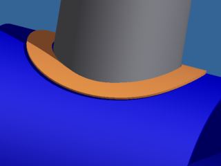
I need to mode a reinforcement ring for a pressure vessel. The ring needs to have a round hole in the middle for the pipe insert. The width of the ring needs to be constant. In the drawing it is the orange part. How can I model this ring?
I need to mode a reinforcement ring for a pressure vessel. The ring needs to have a round hole in the middle for the pipe insert. The width of the ring needs to be constant. In the drawing it is the orange part. How can I model this ring?
63 REPLIES 63
Message 21 of 64
03-31-2010
10:29 AM
- Mark as New
- Bookmark
- Subscribe
- Mute
- Subscribe to RSS Feed
- Permalink
- Report
03-31-2010
10:29 AM
Dennis,
Do you know why sheet metal rejects the swept part in my saddle2? I posted the error message I got right after it, something about "multiple bodies" I think, but I don't know what it's talking about. I hardly ever use sheet metal so I don't know that much about it.
Thanks
Do you know why sheet metal rejects the swept part in my saddle2? I posted the error message I got right after it, something about "multiple bodies" I think, but I don't know what it's talking about. I hardly ever use sheet metal so I don't know that much about it.
Thanks
Message 22 of 64
03-31-2010
10:33 AM
- Mark as New
- Bookmark
- Subscribe
- Mute
- Subscribe to RSS Feed
- Permalink
- Report
03-31-2010
10:33 AM
The width doesn't look very constant to me. (Maybe it's my monitor:)
Message 23 of 64
03-31-2010
10:57 AM
- Mark as New
- Bookmark
- Subscribe
- Mute
- Subscribe to RSS Feed
- Permalink
- Report
03-31-2010
10:57 AM
sorry I was thinking Thickness rather than Width.
So what about the attached part, doesn't this meet the OP's criteria?
ipt is 2010 version
roll End of Part down
So what about the attached part, doesn't this meet the OP's criteria?
ipt is 2010 version
roll End of Part down
Message 24 of 64
03-31-2010
12:01 PM
- Mark as New
- Bookmark
- Subscribe
- Mute
- Subscribe to RSS Feed
- Permalink
- Report
03-31-2010
12:01 PM
Your O.D. is a circle in the flat pattern but the I.D. is ... What is it? It's not an ellipse, there has to be a name for it. Anyway that looks like the easiest way to get close, but as you work towards the extremes you can see it still is not a truly uniform width.
Perhaps it would be best to reexamine the requirement to see exactly what we can get away with, i.e. why do we think we want the width the same all around, is it some sort of welding requirement, is it for some sort of strength consideration, is it purely aesthetic? There is might be an easier way to address any of these concerns without strictly adhering to the requirement we are trying to work under.
Perhaps it would be best to reexamine the requirement to see exactly what we can get away with, i.e. why do we think we want the width the same all around, is it some sort of welding requirement, is it for some sort of strength consideration, is it purely aesthetic? There is might be an easier way to address any of these concerns without strictly adhering to the requirement we are trying to work under.
Message 25 of 64
03-31-2010
12:27 PM
- Mark as New
- Bookmark
- Subscribe
- Mute
- Subscribe to RSS Feed
- Permalink
- Report
03-31-2010
12:27 PM
Can you make anything out of saddle2 that I posted earlier?
I think that would be the best if only it actually worked.
(I had an idea but it chose to crash rather that let me try it.)
I think that would be the best if only it actually worked.
(I had an idea but it chose to crash rather that let me try it.)
Message 26 of 64
03-31-2010
12:41 PM
- Mark as New
- Bookmark
- Subscribe
- Mute
- Subscribe to RSS Feed
- Permalink
- Report
03-31-2010
12:41 PM
Boo-ya!
But seriously, there's got to be something wrong with it. I do see a funky little flaw near the bottom on the edge, there's probably more problems. But I think that's pretty close to what we need.
But seriously, there's got to be something wrong with it. I do see a funky little flaw near the bottom on the edge, there's probably more problems. But I think that's pretty close to what we need.
Message 27 of 64
03-31-2010
07:14 PM
- Mark as New
- Bookmark
- Subscribe
- Mute
- Subscribe to RSS Feed
- Permalink
- Report
03-31-2010
07:14 PM
Just use surfaces. Use a surface to create the pressure vessel shape. Use and arc not a circle (for flatteneing). Then use another surface to intersect. Trim until you have only the collar. Thicken the collar surface, convert to sheet metal and flatten.
See attached.
See attached.
Message 28 of 64
03-31-2010
07:15 PM
- Mark as New
- Bookmark
- Subscribe
- Mute
- Subscribe to RSS Feed
- Permalink
- Report
Message 29 of 64
03-31-2010
08:35 PM
- Mark as New
- Bookmark
- Subscribe
- Mute
- Subscribe to RSS Feed
- Permalink
- Report
03-31-2010
08:35 PM
why don't you simlply make a circle with a hole in the centre and then bend it using bend command in the modify panel.
is that not working?
is that not working?
Message 30 of 64
03-31-2010
09:47 PM
- Mark as New
- Bookmark
- Subscribe
- Mute
- Subscribe to RSS Feed
- Permalink
- Report
03-31-2010
09:47 PM
That would work too. I just prefer the surfaces way since the sketches can be derived and remain associative to existing geometry where the bend command requires typed input. The bend way is faster though. Seems to flatten ok as well.
Message 31 of 64
03-31-2010
10:07 PM
- Mark as New
- Bookmark
- Subscribe
- Mute
- Subscribe to RSS Feed
- Permalink
- Report
03-31-2010
10:07 PM
You just can't make a bended circle, because the pipe won't fit in the hole. When you bend it the hole is not round anymore.
Message 32 of 64
03-31-2010
10:24 PM
- Mark as New
- Bookmark
- Subscribe
- Mute
- Subscribe to RSS Feed
- Permalink
- Report
03-31-2010
10:24 PM
I think you are getting far too carried away about trying to get the equal spacing all the way around. Do you know how inaccurate the area replacement method is for nozzle reinforcement, particularly on larger nozzles? Don't forget your pad can always be larger, you just can't count the additional area in your reinforcement calculations.
I don't use this method for my pressure vessels but if you want equal width, the see attached. It is not exact but pretty close and easy to create.
Stew
I don't use this method for my pressure vessels but if you want equal width, the see attached. It is not exact but pretty close and easy to create.
Stew
Please mark as "Accept as Solution" if it answers your question or "Kudos" if you found it useful.
---------------------------------------------------------------------------------------------------------------------
Stew, AICP
Inventor Professional 2013, Autodesk Simulation Multiphysics 2013
Windows 7 x64 Core i7 32GB Ram FX2000
---------------------------------------------------------------------------------------------------------------------
Stew, AICP
Inventor Professional 2013, Autodesk Simulation Multiphysics 2013
Windows 7 x64 Core i7 32GB Ram FX2000
Message 33 of 64
03-31-2010
10:27 PM
- Mark as New
- Bookmark
- Subscribe
- Mute
- Subscribe to RSS Feed
- Permalink
- Report
03-31-2010
10:27 PM
Oh come on,
then do not make a hole before bending. extrude hole after bending.
it will give you straight thru hole.
it can be flat patterned also.
then do not make a hole before bending. extrude hole after bending.
it will give you straight thru hole.
it can be flat patterned also.
Message 34 of 64
03-31-2010
10:27 PM
- Mark as New
- Bookmark
- Subscribe
- Mute
- Subscribe to RSS Feed
- Permalink
- Report
03-31-2010
10:27 PM
Don't worry about the hole, the re-pad is cut with spare, the edge is manually prep'ed to suit the code and the weld procedure.
Please mark as "Accept as Solution" if it answers your question or "Kudos" if you found it useful.
---------------------------------------------------------------------------------------------------------------------
Stew, AICP
Inventor Professional 2013, Autodesk Simulation Multiphysics 2013
Windows 7 x64 Core i7 32GB Ram FX2000
---------------------------------------------------------------------------------------------------------------------
Stew, AICP
Inventor Professional 2013, Autodesk Simulation Multiphysics 2013
Windows 7 x64 Core i7 32GB Ram FX2000
Message 35 of 64
03-31-2010
10:36 PM
- Mark as New
- Bookmark
- Subscribe
- Mute
- Subscribe to RSS Feed
- Permalink
- Report
03-31-2010
10:36 PM
oh now I get it. If you must have equal thickness then just edit the flat pattern. In flat pattern mode create a sketch, project the inner hole as a construction line (which is not a perfect circle), then offset it to the narrowest edge, then draw an oversize circle and use the cut feature to remove the excess. The flat pattern now has uniform thickness.
Message 36 of 64
04-01-2010
02:12 AM
- Mark as New
- Bookmark
- Subscribe
- Mute
- Subscribe to RSS Feed
- Permalink
- Report
04-01-2010
02:12 AM
When you flat pattern after the inner hole is cut you get an eliptical shape. But the outer shape is still round so that you don't have a constant width. I'm gonna inspect the model which is made by the sweep. That one looks very interesting.
Message 37 of 64
04-01-2010
02:44 AM
- Mark as New
- Bookmark
- Subscribe
- Mute
- Subscribe to RSS Feed
- Permalink
- Report
04-01-2010
02:44 AM
To clear up some misunderstandings I give an example of the size:
Outerdiameter vessel: 1024mm
Outer diameter pipe: 518mm
Thickness repad: 10mm
Width repad: 100mm
Outerdiameter vessel: 1024mm
Outer diameter pipe: 518mm
Thickness repad: 10mm
Width repad: 100mm
Message 38 of 64
04-01-2010
03:16 AM
- Mark as New
- Bookmark
- Subscribe
- Mute
- Subscribe to RSS Feed
- Permalink
- Report
04-01-2010
03:16 AM
Like this....
Flat pattern for cutting is constant 100mm wide. Model will be wider at extremes of bend.
Flat pattern for cutting is constant 100mm wide. Model will be wider at extremes of bend.
Message 39 of 64
04-01-2010
05:42 AM
- Mark as New
- Bookmark
- Subscribe
- Mute
- Subscribe to RSS Feed
- Permalink
- Report
04-01-2010
05:42 AM
I proposed that solution days ago. It was rejected or ignored.
--
Dennis Jeffrey, Autodesk Inventor Certified Expert
Subscribe to the free "The Creative Inventor Magazine now available at:
http://teknigroup.com/CI-Subscribe-Login.asp
--
Dennis Jeffrey, Autodesk Inventor Certified Expert
Subscribe to the free "The Creative Inventor Magazine now available at:
http://teknigroup.com/CI-Subscribe-Login.asp
Message 40 of 64
04-01-2010
05:59 AM
- Mark as New
- Bookmark
- Subscribe
- Mute
- Subscribe to RSS Feed
- Permalink
- Report
04-01-2010
05:59 AM
As Stew says above, FOR CALCULATION PURPOSES, this is no doubt overkill. The reality is that in the shop, the fabricator will oversize to some degree based on fab methods. From a code standpoint, the formulas are inherently conservative, and again, the reality is that no engineer in their right mind would normally list 3.94" as a repad width on a fab drawing.
HOWEVER...
There ARE times when a vessel head is a very busy place, and trying to find a landing spot for a new bracket/ nozzle/whatever really does get to be a challenge. So I generally like to model repads as accurately as possible. They're a bit of a challenge, and there are several approaches. I've attached the method I like.
Todd
Product Design Collection (Inventor Pro, 3DSMax, HSMWorks)
Fusion 360 / Fusion Team
Reply
Topic Options
- Subscribe to RSS Feed
- Mark Topic as New
- Mark Topic as Read
- Float this Topic for Current User
- Bookmark
- Subscribe
- Printer Friendly Page
Forums Links
Can't find what you're looking for? Ask the community or share your knowledge.
Post to forums
