Community
- Forums Home
- >
- Inventor Community
- >
- Inventor Forum
- >
- Cannot extrude DWG imported into inventor sketch - made in CorelDraw
Inventor Forum
Welcome to Autodesk’s Inventor Forums. Share your knowledge, ask questions, and explore popular Inventor topics.
Turn on suggestions
Auto-suggest helps you quickly narrow down your search results by suggesting possible matches as you type.
Cannot extrude DWG imported into inventor sketch - made in CorelDraw
33 REPLIES 33
SOLVED
Reply
Topic Options
- Subscribe to RSS Feed
- Mark Topic as New
- Mark Topic as Read
- Float this Topic for Current User
- Bookmark
- Subscribe
- Printer Friendly Page
Message 1 of 34
Anonymous
7746 Views, 33 Replies
02-25-2017
06:16 PM
- Mark as New
- Bookmark
- Subscribe
- Mute
- Subscribe to RSS Feed
- Permalink
- Report
02-25-2017
06:16 PM
Hi,
I have a logo I am importing from corelDrawX6 as .dwg or .dxf . I can successfully import it into a sketch in Inventor and can modify and edit it. However, whatever I do I cannot close the curve and extrude it. I have tried using the sketch doctor in several occasions and it either fails to close the curve or the Inventor crashes.
Please help! ![]()
Solved! Go to Solution.
Solved by saltedfish. Go to Solution.
33 REPLIES 33
Message 2 of 34
02-26-2017
06:38 AM
- Mark as New
- Bookmark
- Subscribe
- Mute
- Subscribe to RSS Feed
- Permalink
- Report
02-26-2017
06:38 AM
@Anonymous wrote:
.... and can modify and edit it.
Can you attach original un-edited dwg file here?
What is your manufacturing tolerance on the geometry?
Message 3 of 34
02-26-2017
07:43 AM
- Mark as New
- Bookmark
- Subscribe
- Mute
- Subscribe to RSS Feed
- Permalink
- Report
02-26-2017
07:43 AM
Hi,
Please find the .dwg attached.
It is a 3D printed file so the tolerances are fairly relaxed.
The problem is that simply redrawing the sketch in Inventor is not an option. There is a lot of detailed artwork inside the shape that I have removed for the purpose of posting it online (I don't have permission to post the artwork). So if it was only the teardrop outline, it wasn't a huge problem to draw it in Inventor using the imported CAD as a template. But I need to figure out how to extrude the artwork (which has the same problem as the outline).
Thanks you for attaching the drawing btw.
Message 4 of 34
Anonymous
in reply to:
Anonymous
02-27-2017
12:53 AM
- Mark as New
- Bookmark
- Subscribe
- Mute
- Subscribe to RSS Feed
- Permalink
- Report
02-27-2017
12:53 AM
Pasting the DWG into Inventor and consequently editing it I see something that I know from Corel. It appears one curve (actually it is) but some connection points are made out of 3 points instead of 2 (startpoint-endpoint). You can see it in the attached picture : when you drag the connection point there is a straight line emerging. I suppose this is playing tricks on you. The intermediate point is too close to the others to create a line in IV and IV also does not know how to clean up the 3-point situation.
I had - in a distant past - the same thing when exporting DXF from our CAD (Intergraph EMS) to Corel. I first started to clean up manually in Corel but ended up by writing a routine that read the DXF, it's only text after all, and checked the coordinates in the 'entities' section. If they were nearly the same I deleted the one in the middle. After that it was easy to get a closed contour in Corel, allowing the contours to accept fill color.
My little EXE - if still existing - will be on a floppy, look it up in Google :-), since it's dating from the previous millenium. Can't help you there. But you can work the manual way. If you edit the curve in Corel (node edit) the triple point nodes stand out by showing up as black squares with a white inside square while the dual point nodes are simply black. If in doubt you can drag around the nodes, the bottom line of the screen will tell you the number of nodes selected. You can delete the third node in Corel, reconnect the other 2 if broken. Sometimes it's hard to see where a curve is broken. In that case get out of "node edit", select a curve and apply line color (other than it is). Where color change stops the line is broken.
If the above does not help then I'm out of ideas 🙂
Alex

Message 5 of 34
Anonymous
in reply to:
Anonymous
02-27-2017
01:26 AM
- Mark as New
- Bookmark
- Subscribe
- Mute
- Subscribe to RSS Feed
- Permalink
- Report
02-27-2017
01:26 AM
Hi,
I could extrude the shape as per below steps:
1. import dwg to sketch 1, ( I created sketch 1 on YZ plane)
2. create new 3d sketch
3. Click on Project to Surface, select YZ plane (or plane on which sketch1 is), select all geometry in sketch1
4. Finish 3d sketch
5. Sketch 1 visibility off
6. create new sketch on YZ plane (or plane on which sketch1 is)
7. project all 3d sketch curves
8. Extrude
Please see attached ipt made with above sequence
Thanks & Regards,
Tushar
Message 6 of 34
Anonymous
in reply to:
Anonymous
02-27-2017
12:05 PM
- Mark as New
- Bookmark
- Subscribe
- Mute
- Subscribe to RSS Feed
- Permalink
- Report
02-27-2017
12:05 PM
Hi,
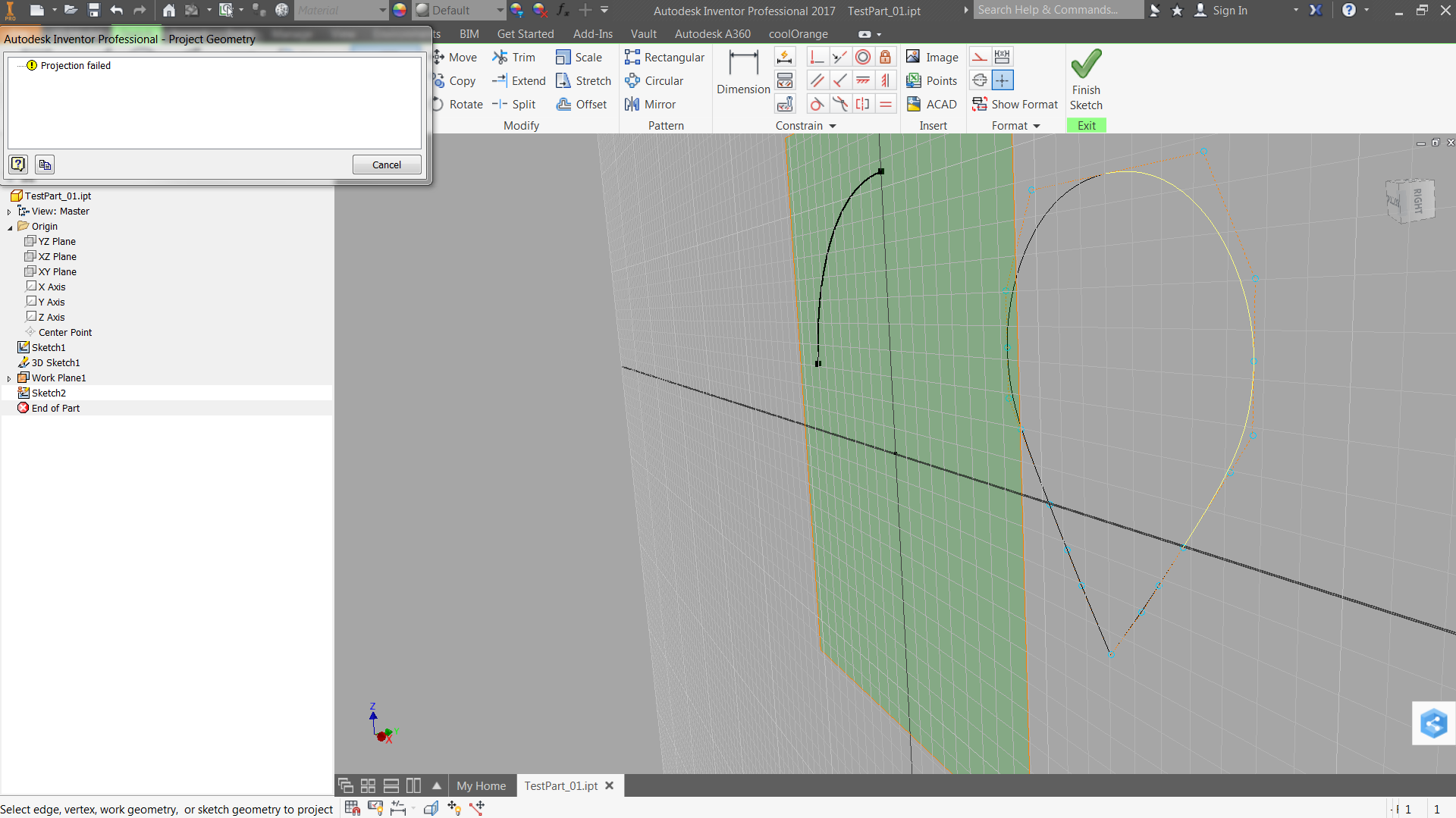
I tried to follow your instructions but did not manage to project the geometry either onto a 3D sketch using "project to surface" or onto a 2D sketch.
See screen caps attached.
Message 7 of 34
Anonymous
in reply to:
Anonymous
02-27-2017
12:14 PM
- Mark as New
- Bookmark
- Subscribe
- Mute
- Subscribe to RSS Feed
- Permalink
- Report
02-27-2017
12:14 PM
Ignore the last post. I was being an idiot 🙂 ... the 2D-3D-2D projection cycle totally worked!!
Thanks so much.
Message 8 of 34
Anonymous
in reply to:
Anonymous
02-28-2017
05:16 AM
- Mark as New
- Bookmark
- Subscribe
- Mute
- Subscribe to RSS Feed
- Permalink
- Report
02-28-2017
05:16 AM
I'm always intrested in the "why". What your method probably does is use an internal cleanup module inside the 3D-sketch. After that there is a clean start for the projected 2D sketch. Would be intresting to see if cleaning up the CDR/DXF file would also work.
Alex
Message 9 of 34
12-13-2017
08:52 AM
- Mark as New
- Bookmark
- Subscribe
- Mute
- Subscribe to RSS Feed
- Permalink
- Report
12-13-2017
08:52 AM
@Anonymous wrote:Hi,
I could extrude the shape as per below steps:
1. import dwg to sketch 1, ( I created sketch 1 on YZ plane)
2. create new 3d sketch
3. Click on Project to Surface, select YZ plane (or plane on which sketch1 is), select all geometry in sketch1
4. Finish 3d sketch
5. Sketch 1 visibility off
6. create new sketch on YZ plane (or plane on which sketch1 is)
7. project all 3d sketch curves
8. Extrude
Please see attached ipt made with above sequence
Thanks & Regards,
Tushar
Hello and sorry for resurrecting an old post.
I get to Step 7 above ('project all 3d sketch curves') and this is where I get stuck. The only button I see even close to that is 'Project to 3D Sketch,' which is the wrong direction. Is there another name or option for this feature, or am I misunderstanding the directions?
Message 10 of 34
12-13-2017
09:06 AM
- Mark as New
- Bookmark
- Subscribe
- Mute
- Subscribe to RSS Feed
- Permalink
- Report
12-13-2017
09:06 AM
@saltedfish wrote:
I get to Step 7 above ('project all 3d sketch curves') and this is where I get stuck. The only button I see even close to that is 'Project to 3D Sketch,' which is the wrong direction. Is there another name or option for this feature, or am I misunderstanding the directions?
Project Geometry and select the curves. (you should be in a 2D sketch)
Message 11 of 34
12-13-2017
09:12 AM
- Mark as New
- Bookmark
- Subscribe
- Mute
- Subscribe to RSS Feed
- Permalink
- Report
12-13-2017
09:12 AM
Gotcha. Is there a way to select multiple by clicking and dragging? I'm trying to project a fairly complicated repeating pattern and don't want to have to select every one of the hundreds of lines.
Message 12 of 34
12-13-2017
11:15 AM
- Mark as New
- Bookmark
- Subscribe
- Mute
- Subscribe to RSS Feed
- Permalink
- Report
12-13-2017
11:15 AM
Maybe you could try it and find out that way?
Sam B
Inventor Professional 2018.2
Vault Workgroup 2018.0
Windows 7 Enterprise 64-bit, SP1
Message 13 of 34
12-13-2017
11:18 AM
- Mark as New
- Bookmark
- Subscribe
- Mute
- Subscribe to RSS Feed
- Permalink
- Report
Message 14 of 34
12-13-2017
11:19 AM
- Mark as New
- Bookmark
- Subscribe
- Mute
- Subscribe to RSS Feed
- Permalink
- Report
12-13-2017
11:19 AM
How about select multiple, then pick the Project Geometry tool?
Sam B
Inventor Professional 2018.2
Vault Workgroup 2018.0
Windows 7 Enterprise 64-bit, SP1
Message 15 of 34
12-13-2017
11:33 AM
- Mark as New
- Bookmark
- Subscribe
- Mute
- Subscribe to RSS Feed
- Permalink
- Report
12-13-2017
11:33 AM
I am in the "Edit Sketch" mode, which reveals the "Project Geometry" button under the "Sketch" ribbon. I click the button, and when I mouse over the segments in the sketch, they change from yellow to white, indicating (I assume) that they can be selected for projection. However, clicking and dragging does not result in the selection box. Nor does shift+click+drag. Nor also ctrl+click+drag.
To be clear, I can individually select segments (using the cursor that looks like the default with a little '+' in the lower right) in the 3D sketch and hit "Finish Sketch," then toggle the visibility on the 3D sketch and am left with whatever segments I clicked on. Extruding works at this point. However, as I indicated earlier, there are easily 400+ segments I need to transfer this way (the drawing is for a multi-part fixture drawn in Esprit), and I'm really hoping there is a faster way.
As an aside, I am assuming the goal here is to import the .dwg, convert it to a 3D sketch, then project the 3D sketch back into a regular 2D sketch, which can then be extruded. Is this more or less the roundabout process here?
Message 16 of 34
12-13-2017
12:05 PM
- Mark as New
- Bookmark
- Subscribe
- Mute
- Subscribe to RSS Feed
- Permalink
- Report
12-13-2017
12:05 PM
Select the segments before invoking the Project Geometry button.
Sam B
Inventor Professional 2018.2
Vault Workgroup 2018.0
Windows 7 Enterprise 64-bit, SP1
Message 17 of 34
12-13-2017
12:44 PM
- Mark as New
- Bookmark
- Subscribe
- Mute
- Subscribe to RSS Feed
- Permalink
- Report
12-13-2017
12:44 PM
That does not appear to work. Let me step through my process and see if you spot what I'm doing wrong:
- New .ipt
- Create sketch on XY plane
- ACAD -> import .dwg
- Import Destination Options -> Finish
- Finish Sketch
- Start 3D Sketch
- Project to Surface -> Faces, select XY plane; Curves, click-and-drag contents of .dwg; Okay
- Finish 3D sketch, hide first sketch so that only 3D sketch is visible
- Right-click XY plane, New Sketch
- Project Geometry
At this point, things break down. Only the 3D sketch is visible at this time, and when I click-and-drag to select the entirety of it, the only thing that gets selected is a little point at the top with an icon similar to the "Project Geometry" icon. If I then click on the 'Project Geometry" button at the top ribbon, the selection is undone, and I am prompted to "Select edge, vertex, work geometry or sketch geometry to project." I am unable to click-and-drag anywhere, and the only things I can highlight are either the segments in the 3D sketch or the "YZ Plane," "XY Plane," etc under "Origin" in the browser bar.
Hopefully this rundown reveals the step I'm missing or misunderstood. Thanks for your time and patience.
Message 18 of 34
12-14-2017
12:58 AM
- Mark as New
- Bookmark
- Subscribe
- Mute
- Subscribe to RSS Feed
- Permalink
- Report
12-14-2017
12:58 AM
Hi! Did you try using DWG Underlay workflow? Start a new part or open an existing part. Create -> Import -> pick the DWG file -> pick a plane and select the origin. The DWG geometry will be linked to Inventor part (or assembly). Then you can create a 2D Sketch and use Project DWG Geometry command to project DWG geometry to the active sketch.
Many thanks!
Johnson Shiue (johnson.shiue@autodesk.com)
Software Test Engineer
Message 19 of 34
12-14-2017
04:32 AM
- Mark as New
- Bookmark
- Subscribe
- Mute
- Subscribe to RSS Feed
- Permalink
- Report
12-14-2017
04:32 AM
Sorry, there doesn't seem to be a way to do what you want. Dragging a window in a sketch produces the window with either dashed (right to left) or solid (left to right) borders as you would expect, but it doesn't actually select anything not already in the sketch. But, as you've pointed out, you're able to select entities from other sketches by individually picking them. This looks like an unnecessary limitation to me. If you post an idea in the Inventor Ideas forum, I will support it.
Sam B
Inventor Professional 2018.2
Vault Workgroup 2018.0
Windows 7 Enterprise 64-bit, SP1
Message 20 of 34
12-14-2017
08:15 AM
- Mark as New
- Bookmark
- Subscribe
- Mute
- Subscribe to RSS Feed
- Permalink
- Report
12-14-2017
08:15 AM
@johnsonshiue wrote:Hi! Did you try using DWG Underlay workflow? Start a new part or open an existing part. Create -> Import -> pick the DWG file -> pick a plane and select the origin. The DWG geometry will be linked to Inventor part (or assembly). Then you can create a 2D Sketch and use Project DWG Geometry command to project DWG geometry to the active sketch.
Many thanks!
Where is this "Create" tab? I found two create sections, one under "3D model" and another under "Sketch." Neither one has an "Import" option. I'm not sure what the "DWG Underlay workflow" is, exactly. I was able to go to File -> Open -> Import DWG, but that just imports the drawing and doesn't appear to allow me to generate a sketch, unless there is that functionality. Thanks for your time!
@SBix26 wrote:
Sorry, there doesn't seem to be a way to do what you want. Dragging a window in a sketch produces the window with either dashed (right to left) or solid (left to right) borders as you would expect, but it doesn't actually select anything not already in the sketch. But, as you've pointed out, you're able to select entities from other sketches by individually picking them. This looks like an unnecessary limitation to me. If you post an idea in the Inventor Ideas forum, I will support it.
Sam B
Inventor Professional 2018.2
Vault Workgroup 2018.0
Windows 7 Enterprise 64-bit, SP1
It's kinda shocking to me that Inventor doesn't allow something as simple as importing a standard file format into it's sketches. I think I will post this there and reference this thread. Thanks a ton for your help in all this!
Reply
Topic Options
- Subscribe to RSS Feed
- Mark Topic as New
- Mark Topic as Read
- Float this Topic for Current User
- Bookmark
- Subscribe
- Printer Friendly Page
Forums Links
Can't find what you're looking for? Ask the community or share your knowledge.
Post to forums
