Community
Fusion Manufacture
Talk shop with the Fusion (formerly Fusion 360) Manufacture Community. Share tool strategies, tips, get advice and solve problems together with the best minds in the industry.
- Forums Home
- >
- Fusion Community
- >
- Manufacture Forum
- >
- Re: operation - parallel
Fusion Manufacture
Talk shop with the Fusion (formerly Fusion 360) Manufacture Community. Share tool strategies, tips, get advice and solve problems together with the best minds in the industry.
Turn on suggestions
Auto-suggest helps you quickly narrow down your search results by suggesting possible matches as you type.
Reply
Topic Options
- Subscribe to RSS Feed
- Mark Topic as New
- Mark Topic as Read
- Float this Topic for Current User
- Bookmark
- Subscribe
- Printer Friendly Page
Message 1 of 28
Anonymous
2416 Views, 27 Replies
09-01-2014
11:56 AM
- Mark as New
- Bookmark
- Subscribe
- Mute
- Subscribe to RSS Feed
- Permalink
- Report
09-01-2014
11:56 AM
Hi
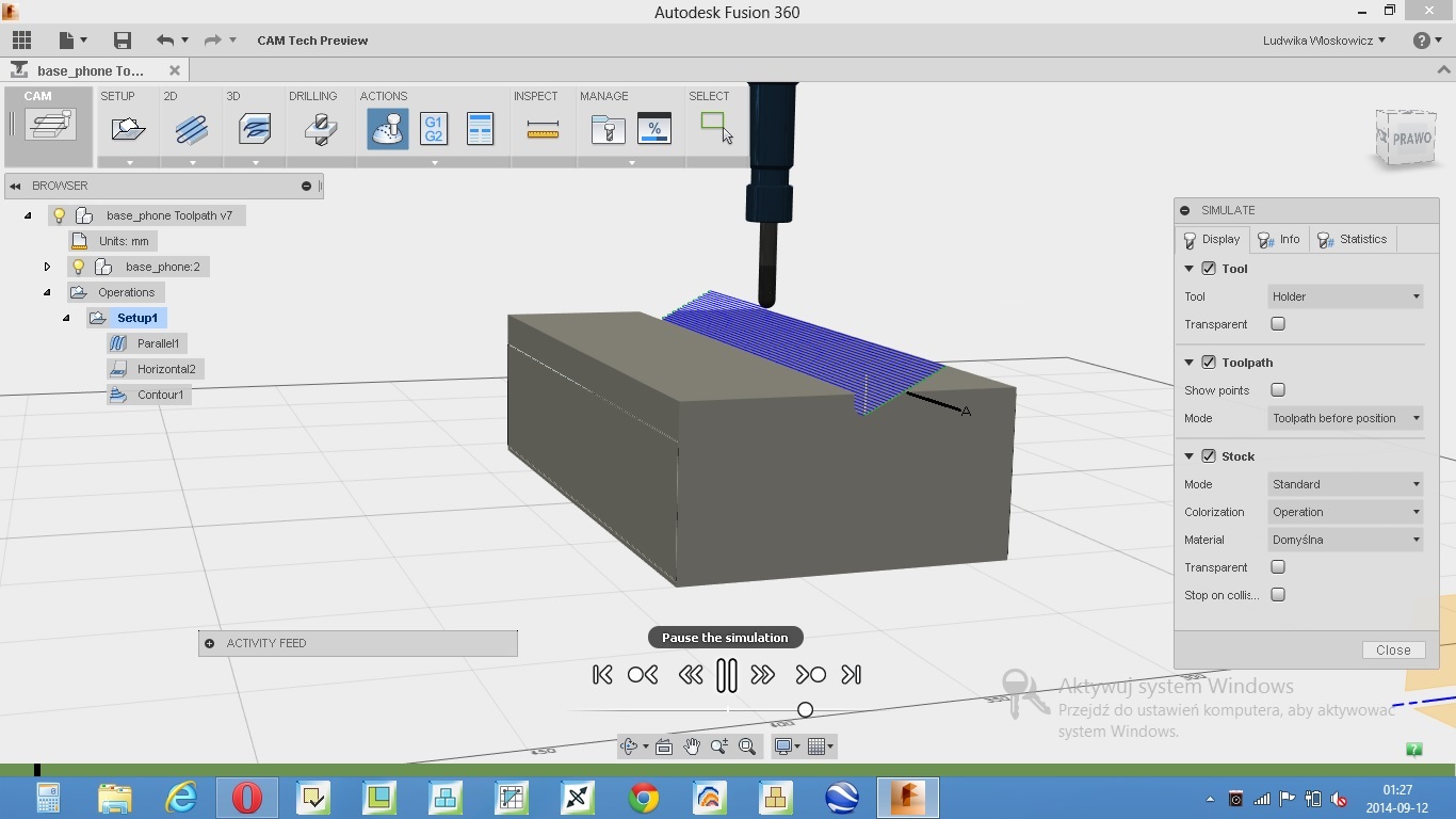
I have a questions. In my toolpath file I put the parallel operation. The geometry which is operated is the part of the plastic injection mold. What parameter controls the course of the optimization path for unnecessary runs - those runs which are shown in attached image? This is the beginning of the path, and then the tool enters deeper into the stock and after all is OK.
Ludwika
Solved! Go to Solution.
Solved by bobvdd. Go to Solution.
27 REPLIES 27
Message 2 of 28
09-02-2014
02:00 PM
- Mark as New
- Bookmark
- Subscribe
- Mute
- Subscribe to RSS Feed
- Permalink
- Report
09-02-2014
02:00 PM
Ludwika,
Have you tried using the Machining Boundary option on teh second tab (Geometry tab) to restrict the toolpath?


Other options are to use the Slope or the Top and Bottom height plane positions to restrict the toolpath.
Bob
Bob Van der Donck
Principal UX designer DMG group
Message 3 of 28
09-02-2014
02:26 PM
- Mark as New
- Bookmark
- Subscribe
- Mute
- Subscribe to RSS Feed
- Permalink
- Report
09-02-2014
02:26 PM
Thanks Bob.
I will try tomorrow, now I'm waiting for update. Maybe I share you this
model with toolpath file.
Ludwika
I will try tomorrow, now I'm waiting for update. Maybe I share you this
model with toolpath file.
Ludwika
Message 4 of 28
Anonymous
in reply to:
Anonymous
09-10-2014
06:13 PM
- Mark as New
- Bookmark
- Subscribe
- Mute
- Subscribe to RSS Feed
- Permalink
- Report
09-10-2014
06:13 PM
Hi Bob.
How can I invite you to the project ,where the file is placed. I dont have your email address. I have still problem with unnecessary runs in the toolpath.
Ludwika
Message 5 of 28
09-11-2014
08:50 AM
- Mark as New
- Bookmark
- Subscribe
- Mute
- Subscribe to RSS Feed
- Permalink
- Report
09-11-2014
08:50 AM
My email address is bob.van.der.donck@autodesk.com.
As an alternative to sharing, you could export the cam360 file by using the File > Export ... menu.
Then send me that file or post it here on the forum.
Thanks.
Bob
Bob Van der Donck
Principal UX designer DMG group
Message 6 of 28
09-11-2014
10:44 AM
- Mark as New
- Bookmark
- Subscribe
- Mute
- Subscribe to RSS Feed
- Permalink
- Report
09-11-2014
10:44 AM
Hi Bob
Toolpath file is attached in email. Main operation is parallel_1 other operatrions are just for test. The problem is with these runs on the ramp surface when the tool begins to mill the cylindrical surface. I dont want these runs . Theoretically, they can be avoided by dividing the operation into three sub-operations :
first - above flat surface,
second - above cylindrical surface
and last above ramp surface
But this not good solution , tool will working in contact with a large vertical surface. So will problem with a stress in the material , in the tool , that can generate deformation in created forms. And of course a lot of unnecessary heat
Ludwika
Message 7 of 28
09-11-2014
12:08 PM
- Mark as New
- Bookmark
- Subscribe
- Mute
- Subscribe to RSS Feed
- Permalink
- Report
09-11-2014
12:08 PM
I think you need to set the contact point boundary checkbox on.
This option is specifically intended to avoid the border overlap that you were concerned about.

You also have set your additional offset to 1 mm, I think it is better to set that back to its default value of 0 as well.
Bob Van der Donck
Principal UX designer DMG group
Message 8 of 28
09-11-2014
04:56 PM
- Mark as New
- Bookmark
- Subscribe
- Mute
- Subscribe to RSS Feed
- Permalink
- Report
09-11-2014
04:56 PM
I made these changes, but they do not affect the path.
Please look at the picture I attached.
Why the tool after reaching point A does not return to milling. All runs up point A are unnecessary. I would like to avoid the milling of the air.
Message 9 of 28
09-12-2014
08:20 AM
- Mark as New
- Bookmark
- Subscribe
- Mute
- Subscribe to RSS Feed
- Permalink
- Report
09-12-2014
08:20 AM
Is it possible that you have a surface that is hidden?
Jeff Walters
Senior Support Engineer, CAM
Senior Support Engineer, CAM
Message 10 of 28
09-12-2014
09:22 AM
- Mark as New
- Bookmark
- Subscribe
- Mute
- Subscribe to RSS Feed
- Permalink
- Report
09-12-2014
09:22 AM
I suspect Ludwika simply selected a too broad boundary. In order to restrict the toolpath to the slanted face, a smaller boundary is necessary.
And that boundary can only be obtained after editing the selection. See this video.
Bob Van der Donck
Principal UX designer DMG group
Message 11 of 28
09-12-2014
09:34 AM
- Mark as New
- Bookmark
- Subscribe
- Mute
- Subscribe to RSS Feed
- Permalink
- Report
09-12-2014
09:34 AM
Yes but having too big of an area would have caused the tool to cut along the flat top. His screen shot looks like it is continuing to cut the angle up and out of the stock well above the part. Unless we have a major bug here the only way I can see that happening is if there is a surface or other part that is hidden.
Jeff Walters
Senior Support Engineer, CAM
Senior Support Engineer, CAM
Message 12 of 28
09-12-2014
11:25 AM
- Mark as New
- Bookmark
- Subscribe
- Mute
- Subscribe to RSS Feed
- Permalink
- Report
09-12-2014
11:25 AM
@jeff.walters wrote:Is it possible that you have a surface that is hidden?
Hi Jeff
There is no hidden surface. The body is made by combine operation
Ludwika
Message 14 of 28
09-12-2014
11:44 AM
- Mark as New
- Bookmark
- Subscribe
- Mute
- Subscribe to RSS Feed
- Permalink
- Report
09-12-2014
11:44 AM
@bobvdd wrote:I suspect Ludwika simply selected a too broad boundary. In order to restrict the toolpath to the slanted face, a smaller boundary is necessary.
And that boundary can only be obtained after editing the selection. See this video.
Hi Bob
Firstly , excuse me , real precision of expression is the first of all. So we are at the beginning of the problem. The boundary selected is the smallest of the selected. In this moment I have no idea what to do . I will try with split operation in the weekend.
Have a nice weekend!
Ludwika
Message 15 of 28
Anonymous
in reply to:
Anonymous
09-15-2014
12:29 PM
- Mark as New
- Bookmark
- Subscribe
- Mute
- Subscribe to RSS Feed
- Permalink
- Report
09-15-2014
12:29 PM
Hi Bob
The problem of milling air is solved. It is importrant to good set value maximum stepdown and value number stepdowns. I had first 4 mm and second 20 ,it was wrong.
But another problem appeared. Now I have set Tool outside boundary and Additional offset 4 mm ( the tool has 6 mm diameter) . The prompt informs that is horizontal offset , OK this horizontal offset but on the bottom height , the tool is falls on the wall of the stock and move for 4 mm ( from the wall of the stock ) , on the bottom height. The offset bottom height is specially set to 20 mm
All stock offsets are 0 mmm .The questions are :
1. Why does the tool fall to the bottom height when Tool outside boundary is set ?
2.Why is offset implemented on the bottom height ?
By me offset should be implemented on the current mill surface.
Bob be so kind and check my model, maybe somewhere my settings are wrong again.
Many thanks for your support.
Ludwika
Message 16 of 28
09-15-2014
01:57 PM
- Mark as New
- Bookmark
- Subscribe
- Mute
- Subscribe to RSS Feed
- Permalink
- Report
09-15-2014
01:57 PM
Ludwika,
I saved a new version of your part.
In Parallel1 operation, I changed the bottom plane to be flush with the top horizontal face of the part rather than 20 mm offset.
I kept Tool outside boundary and I also kept the additional offset of 4mm.
Here is a side view of the resulting toolpath. Is that what you were hoping to get?

Bob Van der Donck
Principal UX designer DMG group
Message 17 of 28
09-15-2014
06:05 PM
- Mark as New
- Bookmark
- Subscribe
- Mute
- Subscribe to RSS Feed
- Permalink
- Report
09-15-2014
06:05 PM
Hi Bob
It looks perfectly for flat surface. Conclusion is that the strategy
*Paralle*l or *Horizontal* with *Tool outside boundary* is proper for flat
surface. For the ramp or cylindrical surface must be applied the other one.
I was looking for but still have not found good.
In all other I have unnecessary runs , I don't why tool falls always
to the *Bottom
height*. The best looks *Pocket* with* Tool center on boundary*. I think
this will be used .
Ludwika
Message 18 of 28
09-17-2014
02:34 PM
- Mark as New
- Bookmark
- Subscribe
- Mute
- Subscribe to RSS Feed
- Permalink
- Report
09-17-2014
02:34 PM
Ludwika,
I can perfectly use Parallel for non-flat surfaces. Parallel is certainly not restricted to flat surfaces.
Here is an example where I use a Parallel with following settings
Tool center on boundary
Additional offset = 0
Bottom height plane at the bottom of the part.

And you can see that the toolpath is nicely contained.
It does not overspill on the sides and it does not go all the way down to the bottom plane either.
Bob
Bob Van der Donck
Principal UX designer DMG group
Message 19 of 28
09-18-2014
01:54 AM
- Mark as New
- Bookmark
- Subscribe
- Mute
- Subscribe to RSS Feed
- Permalink
- Report
09-18-2014
01:54 AM
Hi
It looks nice, but when I changed tool - flat mill 22 mm diam. instead ball mill and angle for 0 deg please look what happened.
The ball mill is the finishing tool , in the first step model should be treated roughly by flat mill. This operation must be carried out with Tool outside boundary option which in this case is cumbersome.
Offset for this option should be other than 0 , the best if it is more than half of tool's diameter. The errors shown on the picture are caused by the lack of offset. The flat mill should works by the lateral surface, but not bottom face. I think that the algorithm of the pararell strategy has an error because it does not detect collision in this moment .
Thanks for your patience with me.
Ludwika
Message 20 of 28
09-18-2014
06:01 AM
- Mark as New
- Bookmark
- Subscribe
- Mute
- Subscribe to RSS Feed
- Permalink
- Report
09-18-2014
06:01 AM
I noticed that the operation has a warning on it. What does the log file say?
Jeff Walters
Senior Support Engineer, CAM
Senior Support Engineer, CAM
Reply
Topic Options
- Subscribe to RSS Feed
- Mark Topic as New
- Mark Topic as Read
- Float this Topic for Current User
- Bookmark
- Subscribe
- Printer Friendly Page
Forums Links
Can't find what you're looking for? Ask the community or share your knowledge.
Post to forums

