Simulation, how to go about this?

Simulation, how to go about this?

Anonymous
Not applicable
2,872 Views
14 Replies
Message 1 of 15

Simulation, how to go about this?

Anonymous
Not applicable

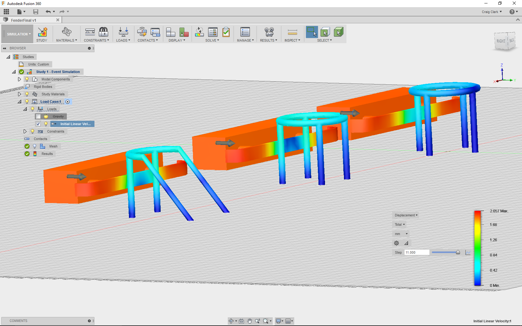
There are two different scenarios in the attached file; the idea is to find the best rotational position for the support legs on the protective cage, so as to protect the charging device from low speed fender impacts.


I think it would be a very educational example for many of us, so if one of the experts could show us the correct way, I for one would be very grateful.

0 Likes
Accepted solutions (1)
2,873 Views
14 Replies
Replies (14)
Message 2 of 15

Andrew.Sartorelli
Alumni
Alumni

Hi @Anonymous,


Interesting end goal, I've got a few suggestions and questions for you to mull over 🙂


What are your failure conditions? When one of the outer columns yields plastically or when center column yields plastically? If we are just concerns with the outer columns then get rid of the inner column, it's just adding elements (computation time) that give us details we aren't interested in.


What loads are you considering? Only in the Y-direction or will you have the fender come in at a skewed angle as well?


I think event simulation is going to be the best analysis type for this model, as it's an impact analysis. Because of that I've got a few tips:

  • Remove an unnecessary details and small features.It seems like you've already, but in general for Event Sim is a good suggestion as the time step size is dictated by the smallest element in the model.
  • Close the gap between the components until they are almost impacting. With Event Sim it's just as computationally intensive to push a model through air as it is to have it impacting a component. Don't waste time simulating your model move through air.
  • Start simple with linear materials before moving onto non-linear materials

In general with simulation you can simulate as many iterations of a design as you want, but it should not be used as substitute for using some basic engineering principles rather use it as a compliment to them. I always recommend to folks to do some hand calculations and figure out when your loads are going to be the most extreme and run just those iterations.


I hope this helps you get started and jumps starts a few things for you to ponder over. Let me know if you have any questions with setting things up.


Regards,

Andrew


Andrew Sartorelli - Autodesk GmbH
Message 3 of 15

Anonymous
Not applicable

Hi Andrew, thanks for taking the time.


The goal of this test is to see which protective cage position protects the centre charger better; this is purely a head on test.

I tried the event simulation after moving things closer but the fender went straight through the protective cage so I must not have done something I should have.


I used the static test and did get what I wanted out of it because of the reference function, if you view the screen shot from the static test you can see the difference between the positions.


To be honest I’m stumbling around in the dark but that’s where I have my most fun, I have attached the file and would appreciate any tips if you have the time.

0 Likes
Message 4 of 15

Andrew.Sartorelli
Alumni
Alumni

Hi @Anonymous,

Thanks for uploading your model! I've had a few things on my plate today so I only got to make 2-3 attempts at the model.I do have however a few more questions for you that will hopefully lead you down the right direction to solving the issues and understanding a bit more about Event Sim. I've hidden my answers behind spoiler tags so you can think about the questions before looking at my answer.


What are the displacement values of fender? What is the gap between the fender and the cage? What is the velocity?

Spoiler
Fender displacement is 0.1mm, the distance between the cage is ~2mm, and the fender is moving at 10mm/s.


Based on these what do you think of the event setup?

Spoiler
In order for contact to occur between the components the duration of the event should be at minimum 0.2second with this geometry and velocity before the gap is closed. This would actually be a very long event simulation though! It would actually be better if the components are touching, my mistake in my last post. I achieved this using a tangent surface on the column and selecting the fender as the reference. Then I used the align command to get them to touching. 


Why is the fender disconnected from the weight? What method can we use in FEA to join bodies together?

Spoiler
There is separation contact defined between them, allowing the parts to detach. We can used bonded contact in FEA to join bodies together. So we should go into contacts and manually change the contact type from separation to bonded.


Hopefully after answering these questions you can make a few changes to your model and start to get results that make more sense. Have you had a chance to review the training content put together on Event Sim yet? It's really great and goes over several different subject areas.


I also noticed that even though the visibility was toggled off for the center charge, they were still being meshed. Because of this I would recommend suppressing them rather than toggling visibility.

Best Regards,
Andrew


Andrew Sartorelli - Autodesk GmbH
Message 5 of 15

Anonymous
Not applicable

Thanks very much for the education Andrew; I plan to work on this when I have some free time on the weekend.

I have not reviewed any material on the Event Sim or any other simulation studies as I am currently deciding if it will be an asset to me in the future.


I will upload the new model after reviewing the material and thinking about your questions before I click the expand tab.

0 Likes
Message 6 of 15

Anonymous
Not applicable

I gave this another shot but still cannot get it to work; I simplified the file by removing all components except for one cage and one body.

The body moves but it does not seem to recognise that there is anything in the way.


I used the static test again and have got some really good results with that, any comments or directions will be much appreciated.

0 Likes
Message 7 of 15

Andrew.Sartorelli
Alumni
Alumni
Accepted solution

Hi @Anonymous,


There is no contact defined in the model. I recommend using the global contacts option to automatically generate separation contact between the components. Contact is one of the ways we can define interactions between different bodies in finite element analysis. If you are seeing to parts not interacting with each other as expected, contact settings would be the first place I would look.


Edit: I also noticed that your initial velocity is very low, 1mm/s, is that correct?


Best Regards,

Andrew


Andrew Sartorelli - Autodesk GmbH
Message 8 of 15

Anonymous
Not applicable

Hi Andrew,


This is one for the water cooler, I haven’t been wearing my glasses when working with Fusion 360 and I thought it said m/s!!!!!!!!!!!!!!!!!!


Anyway my bad eyesight may help others because the attached screen shot is the result of inputting an extremely low velocity.

I did not use contacts on the last file I uploaded because when I did, I received that error message and when I did not use contacts the simulation was solved without an error.


Thanks for your perseverance and sorry for wasting your time, I have attached an image of 1m/s and will upload the results of study I wanted to conduct when I have some time on the weekend.

0 Likes
Message 9 of 15

Andrew.Sartorelli
Alumni
Alumni

Hi @Anonymous,


Glad to hear things are resolved! Don't apologize about my time, supporting folks getting their analysis running is what I get paid for and I always enjoy learning some new things along the way!


Mit freundlichen Grüssen,

Andrew


Andrew Sartorelli - Autodesk GmbH
0 Likes
Message 10 of 15

Anonymous
Not applicable

I redid this simulation and got results that I really did not expect.

After Andrews help, using the simulation software and thinking about it, I now understand why my original conclusion was incorrect.

0 Likes
Message 11 of 15

jeremy.wiesner
Alumni
Alumni

Hello @Anonymous,


Your simulation results are looking very good! I want to add one additional bit of advice. Considering the large amount of deformation that you're observing in your model, I highly recommend using a nonlinear material model. In the screenshot you provided, you can tell there's certainly going to be some permanent, plastic deformation in your parts, which is extremely important to the accuracy of your solution. If you're only using elastic materials and deforming your model to this degree, the solution is not going to be realistic. Fortunately, with last week's Fusion update, there is a new material library called "Fusion 360 Nonlinear Material Library". There are presently 12 nonlinear material models in this library for various metals (steel, aluminum, copper and titanium). I suggest updating your model to use metals out of this library and try running the simulation again to see how how the results change.


Jeremy Wiesner

Research Engineer, Fusion 360 Event Simulation
0 Likes
Message 12 of 15

Anonymous
Not applicable

Thanks very much for the advice Jeremy, I will rework the simulation as you have suggested and post the results.

0 Likes
Message 13 of 15

Anonymous
Not applicable

Hi Jeremy,


I ran the simulation again with the new materials but did not see that much difference, I should have mentioned that the results I posted were adjusted and not actual.


I have attached the actual results from the latest simulation, I have also attached two images of a Linear Global load simulation and a Structural Load simulation, the Event simulation results are giving different results.


The Event simulation results indicate that the protective cage is best placed with one upright tube taking all of the impact, whereas the other two sets of results indicates that the modified cage on the end is the winner?

0 Likes
Message 14 of 15

Andrew.Sartorelli
Alumni
Alumni

Hi @Anonymous,


Personally, I would be more trusting of the Event Sim results. With the other two analyses you are trying to mimic a high speed transient event with a static analysis, which I'm not sure of the validity of. Myself and others are Autodesk will be glad to guide you through workflows and give you pointers on using the simulation environment. But at the end of the day it's up to you the engineer to validate and decide which analysis you will accept as the final result. If we were to tell you a certain analysis is correct/right, then we would be providing engineering guidance which could lead to Autodesk and the individual being liable for the outcome of said analysis.


Best Regards,

Andrew


Andrew Sartorelli - Autodesk GmbH
0 Likes
Message 15 of 15

Anonymous
Not applicable

Hi Andrew,


Autodesk’s position and the fact that we are dealing with software that is being developed are well understood, my actions are purely exploratory.

What you have stated about engineers being responsible for the validation of results is 100% correct, far too many so called engineers have become dependent on software and have lost the feel that is required much of the time in engineering.


My gut feeling on this was that the Event simulation results were incorrect because two uprights bearing the brunt of the impact should be better than one.

I thought about it and came to the conclusion that the fender may be the object which is causing the single upright to produce better results, and as you can see from the attached image I was correct.


The attached image shows the Event simulation redone with the fender removed and the results are much closer to what I originally expected, so that leads to another interesting scenario!


Many thanks to yourself and all the other Autodesk employees who have helped me on this, it has been fun and I feel I am starting to have a good understanding of the simulation environment.