Community
- Forums Home
- >
- Fusion Community
- >
- Design, Validate & Document forum
- >
- Re: Sheet metal: Flange miter with angle..
Fusion Design, Validate & Document
Stuck on a workflow? Have a tricky question about a Fusion (formerly Fusion 360) feature? Share your project, tips and tricks, ask questions, and get advice from the community.
Turn on suggestions
Auto-suggest helps you quickly narrow down your search results by suggesting possible matches as you type.
Reply
Topic Options
- Subscribe to RSS Feed
- Mark Topic as New
- Mark Topic as Read
- Float this Topic for Current User
- Bookmark
- Subscribe
- Printer Friendly Page
Message 1 of 21
11-15-2017
10:45 PM
- Mark as New
- Bookmark
- Subscribe
- Mute
- Subscribe to RSS Feed
- Permalink
- Report
11-15-2017
10:45 PM
Hi friends!
Here`s a problem i stuck with for a while...
Below you can find the link with nonstandard geometry sheet metal panel.
Could you help me, is there any way to miter the flanges manually?
I know that if flanges were with same angles, miter flanges should be cut with angle automatically. But here`s another situation...
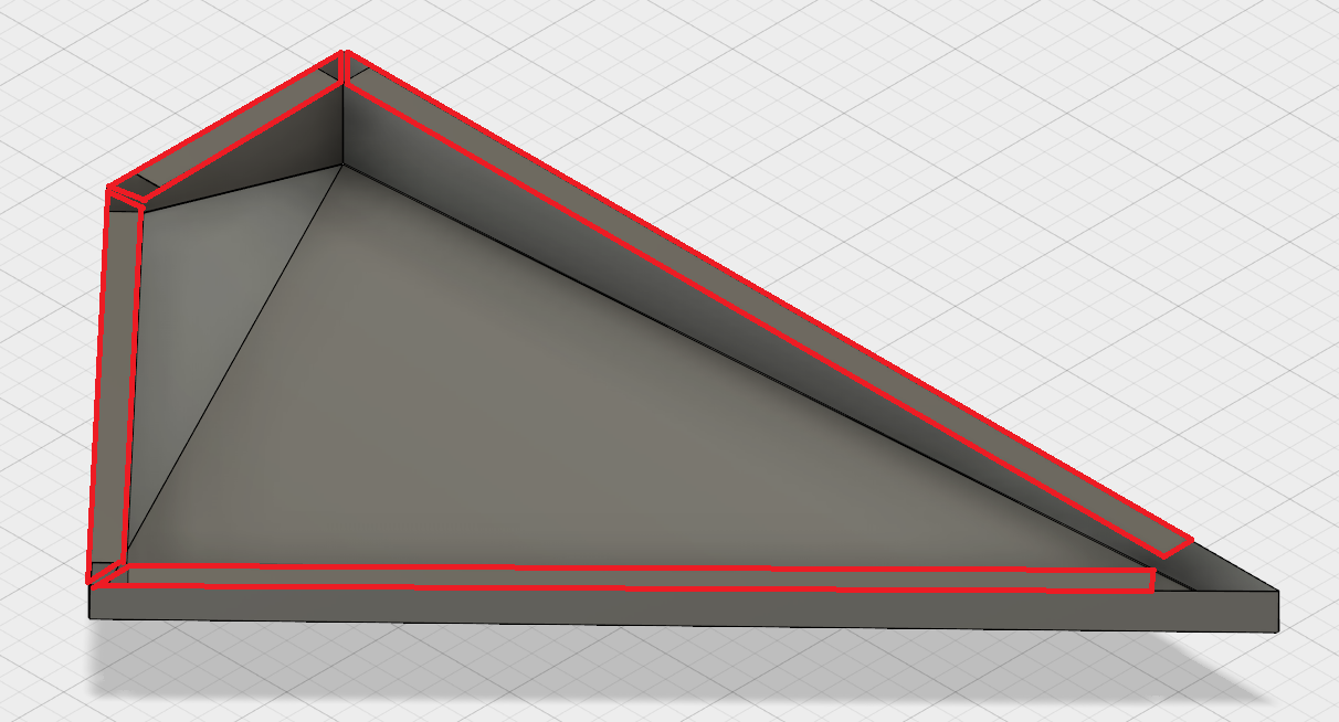
Attached pic. how it should look.
Thank you!
Solved! Go to Solution.
Solved by TheCADWhisperer. Go to Solution.
20 REPLIES 20
Message 2 of 21
11-16-2017
12:25 AM
- Mark as New
- Bookmark
- Subscribe
- Mute
- Subscribe to RSS Feed
- Permalink
- Report
11-16-2017
12:25 AM
While far from ideal, you can create a flange and use the Move/Copy tool to rotate the edge of the created flange. Suppress that flange and create the next one and rotate its sides and so on.
If you choose to do this I would definitely wait until you're as certain as possible that it won't change.
Message 3 of 21
11-16-2017
12:38 AM
- Mark as New
- Bookmark
- Subscribe
- Mute
- Subscribe to RSS Feed
- Permalink
- Report
11-16-2017
12:38 AM
If you extend each of those flanges to the full length of the edge, you can use a sketch to Extrude|Cut the corners to fit.
ETFrench
Message 4 of 21
11-16-2017
12:54 AM
- Mark as New
- Bookmark
- Subscribe
- Mute
- Subscribe to RSS Feed
- Permalink
- Report
11-16-2017
12:54 AM
Could you explain more detailed, how can i Move the edge of the flange? I found only the way to move and rotate faces not edges, and can`t imagine, how can it help to solve the problem...
Tried to chamfer flanges, but when trying to make new flange, they stick together...
Attached one more file to explain issue.
Message 5 of 21
11-16-2017
12:57 AM
- Mark as New
- Bookmark
- Subscribe
- Mute
- Subscribe to RSS Feed
- Permalink
- Report
Message 6 of 21
11-16-2017
12:59 AM
- Mark as New
- Bookmark
- Subscribe
- Mute
- Subscribe to RSS Feed
- Permalink
- Report
11-16-2017
12:59 AM
Have a look at the attached file it's one way to do it
Win10 pro | 16 GB ram | 4 GB graphics Quadro K2200 | Intel(R) 8Xeon(R) CPU E5-1620 v3 @ 3.50GHz 3.50 GHz
Daniel Lyall
The Big Boss
Mach3 User
My Websight, Daniels Wheelchair Customisations.
Facebook | Twitter | LinkedIn
Message 7 of 21
11-16-2017
01:04 AM
- Mark as New
- Bookmark
- Subscribe
- Mute
- Subscribe to RSS Feed
- Permalink
- Report
11-16-2017
01:04 AM
daniel_lyall wrote:
Have a look at the attached file it's one way to do it
If you`ll look carefully at my model, you`ll find out that there`s no any 90 degrees angles so the flanges can`t automatically miter. That`s the main problem. Can`t find way to miter manually as I could easily do in Solidworks...
Message 8 of 21
11-16-2017
01:09 AM
- Mark as New
- Bookmark
- Subscribe
- Mute
- Subscribe to RSS Feed
- Permalink
- Report
11-16-2017
01:09 AM
After you make the first flange then after on a attached flange on the right side of the flange dialog is the full edge drop down, in there you have the option to change the flange width a few different ways.
If the bottom is going to be flat make it as one part not two different flanges so you can bring them up as one then when you do the horizontal flange do it the same way as one then it works how you wont it to, after that you use the extrude command or the move command to move a face, or lay it flat and sketch what you wont to cut out then extrude cut to cut it out..
Win10 pro | 16 GB ram | 4 GB graphics Quadro K2200 | Intel(R) 8Xeon(R) CPU E5-1620 v3 @ 3.50GHz 3.50 GHz
Daniel Lyall
The Big Boss
Mach3 User
My Websight, Daniels Wheelchair Customisations.
Facebook | Twitter | LinkedIn
Message 9 of 21
11-16-2017
01:13 AM
- Mark as New
- Bookmark
- Subscribe
- Mute
- Subscribe to RSS Feed
- Permalink
- Report
11-16-2017
01:13 AM

That half circle above the arrow you use that to set the angle ![]()
Win10 pro | 16 GB ram | 4 GB graphics Quadro K2200 | Intel(R) 8Xeon(R) CPU E5-1620 v3 @ 3.50GHz 3.50 GHz
Daniel Lyall
The Big Boss
Mach3 User
My Websight, Daniels Wheelchair Customisations.
Facebook | Twitter | LinkedIn
Message 10 of 21
11-16-2017
03:20 AM
- Mark as New
- Bookmark
- Subscribe
- Mute
- Subscribe to RSS Feed
- Permalink
- Report
11-16-2017
03:20 AM
daniel_lyall wrote:
After you make the first flange then after on a attached flange on the right side of the flange dialog is the full edge drop down, in there you have the option to change the flange width a few different ways.
If the bottom is going to be flat make it as one part not two different flanges so you can bring them up as one then when you do the horizontal flange do it the same way as one then it works how you wont it to, after that you use the extrude command or the move command to move a face, or lay it flat and sketch what you wont to cut out then extrude cut to cut it out..
You are telling basics. But this doesn`t work...
If I extrude them all at the same time, they just stick together...

Message 11 of 21
11-16-2017
06:14 AM
- Mark as New
- Bookmark
- Subscribe
- Mute
- Subscribe to RSS Feed
- Permalink
- Report
11-16-2017
06:14 AM
There is a robust (fairly simple), fully parametric technique.
If I find the time, I will present a solution.
Hint: Hybrid surface/solid modeling with end result of valid sheet metal folded and flat pattern.
Message 12 of 21
11-16-2017
06:23 AM
- Mark as New
- Bookmark
- Subscribe
- Mute
- Subscribe to RSS Feed
- Permalink
- Report
11-16-2017
06:23 AM
TheCADWhisperer wrote:
There is a robust (fairly simple), fully parametric technique.
If I find the time, I will present a solution.
Hint: Hybrid surface/solid modeling with end result of valid sheet metal folded and flat pattern.
I`ll be waiting for your technique as hard as possible, because that`s the most important feature in my practice.
How can I sleep now, knowing that there`s a solution?
Hope you`ll find time sometimes, thank you! ![]()
Message 14 of 21
11-21-2017
07:58 AM
- Mark as New
- Bookmark
- Subscribe
- Mute
- Subscribe to RSS Feed
- Permalink
- Report
11-21-2017
07:58 AM
My holiday starts tomorrow when hopefully I will get a chance to create a video.
This question comes up here so often since sheet metal tools were introduced that I want to create a video that will once and for all time put it to rest.
Key rules:
1. Sheet metal is uniform thickness throughout.
2. Cuts are perpendicular to flat.
3. Bends are cylindrical or conical. (in current release)
4. Faces should not interfere (in folder or in flat pattern) (this should be obvious without saying, but....).
With those three foundational rules in mind - hybrid techniques can be used to generate sheet metal parts.
Often the hybrid approach is far more flexible and easier than the canned tools.
Message 15 of 21
11-21-2017
01:00 PM
- Mark as New
- Bookmark
- Subscribe
- Mute
- Subscribe to RSS Feed
- Permalink
- Report
11-21-2017
01:00 PM
I was referring to using the Move/Copy tool to grab the edge face and rotate it. To avoid messing up the seam between vertical faces, it's best to split the side face before changing the angle. This is not an ideal solution but will give you a part that unfolds.
Message 16 of 21
11-22-2017
11:37 AM
- Mark as New
- Bookmark
- Subscribe
- Mute
- Subscribe to RSS Feed
- Permalink
- Report
Message 17 of 21
11-22-2017
10:57 PM
- Mark as New
- Bookmark
- Subscribe
- Mute
- Subscribe to RSS Feed
- Permalink
- Report
11-22-2017
10:57 PM
It's insane!
Thank you very much for tutor, that`is definitely what it had to be!
Message 18 of 21
06-19-2018
02:55 AM
- Mark as New
- Bookmark
- Subscribe
- Mute
- Subscribe to RSS Feed
- Permalink
- Report
06-19-2018
02:55 AM
Thank you, TheCADWhisperer for your amazing Titanic work!
I tried to repeat all operation you showed in video with some of mine changes=)
1st of all, I wanted to make all scales parametric(size = 1052 ; size 265; angle 45 degr; size = 41; size=60; size=30)
2nd, I wanted to make changes in Sheet metal Rules, for example Steel thickness, and connect this with filet operation.
This are all main changes that I wanted to realize.
I succeed with everything accept only one parameter - Angle 45 degr.
There is a problem with Sketch 3, that you used to make 2nd split operation. When I try to change angle for number less than 30 or more than 55 degree, all lines start cross each over and the contour crosses itself. So Fusion showing error message.
I realize that to fix it, Id better to make another contour. But maybe you have better decision.
Hope you could teach us some new feature
And I think, it good to know for everyone who wanna make same model to know about this problem.
With best regard.
Message 19 of 21
06-19-2018
04:12 AM
- Mark as New
- Bookmark
- Subscribe
- Mute
- Subscribe to RSS Feed
- Permalink
- Report
Message 20 of 21
06-19-2018
04:34 AM
- Mark as New
- Bookmark
- Subscribe
- Mute
- Subscribe to RSS Feed
- Permalink
- Report
06-19-2018
04:34 AM
Hope everything will work
Reply
Topic Options
- Subscribe to RSS Feed
- Mark Topic as New
- Mark Topic as Read
- Float this Topic for Current User
- Bookmark
- Subscribe
- Printer Friendly Page
Forums Links
Can't find what you're looking for? Ask the community or share your knowledge.
Post to forums
