How to Split body and automatically create tongue and groove around outside wall to fit halves together snugly

How to Split body and automatically create tongue and groove around outside wall to fit halves together snugly

ComputerAidedDisaster
Participant Participant
3,859 Views
38 Replies
Message 1 of 39

How to Split body and automatically create tongue and groove around outside wall to fit halves together snugly

ComputerAidedDisaster
Participant
Participant

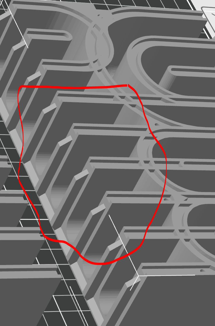
Can someone please explain how I can reproduce this tongue/groove effect when splitting a body (such as a box) into two halves?  

The resulting enclsure needs to be as close to air-tight as possible after printing and re-joining, so this seems like the ideal approach (and it is is commonly found in STL files others have created for speaker enclosures)... but I can't seem to find the right search terms that result in the workflow I am looking for.  


Any help would be greatly appreciated!


--Sean


0 Likes
Accepted solutions (1)
3,860 Views
38 Replies
Replies (38)
Message 2 of 39

TheCADWhisperer
Consultant
Consultant

@ComputerAidedDisaster 

Can you File>Export your *.f3d file to your local drive and then Attach it here to a Reply?

Or a dummy file that can be used to illustrate the process of creating a surface body to use for Split - Body.

0 Likes
Message 3 of 39

ComputerAidedDisaster
Participant
Participant

Sure.   Thanks for the help!


0 Likes
Message 4 of 39

TheCADWhisperer
Consultant
Consultant

@ComputerAidedDisaster 

The geometry is poor quality.

Are you willing to start over from scratch with step-by-step instructions?

0 Likes
Message 5 of 39

ComputerAidedDisaster
Participant
Participant

If that is the only option, I suppose... (and I appreciate the assistance either way, please don't think I am ungrateful)... but that defeats what I'm trying to do, in this case.

I'm trying to take someone's existing design (stl unfortunately) that is fairly close to what I need, and convert it from mesh to solid, make the adjustments I need to get it the rest of the way to what I need, and add the tongue/groove so the split can be re-sealed and nearly air tight when finished....

Is there really no way to modify existing, lower quality geometry (i.e. mesh from an STL import) to get it to the point it can be edited this way?

0 Likes
Message 6 of 39

ComputerAidedDisaster
Participant
Participant
If you happen to know how I could rehabilitate a low-quality mesh pulled
from some other design, that would be most helpful (Not just for this
design but also others I have encountered that I wanted to modify).

That said, if the quality of the existing mesh can't be overcome to make
it possible to modify, but you can show me how you would do it with a
plain, empty cube shape, that will still be very helpful as I haven't
been able to figure out on my own nor can I find a decent example by
searching online
At least I'll know I won't be stuck on the "split with groove"
requirement toward the end.


Either way, I'll gladly take whatever help you are able to offer  🙂

Thanks again

0 Likes
Message 7 of 39

TheCADWhisperer
Consultant
Consultant

@ComputerAidedDisaster 

I have a little more work to do on the model to optimize and then I will lay out the steps...

Box.png

Message 8 of 39

TheCADWhisperer
Consultant
Consultant

@ComputerAidedDisaster 

Start a new part file.

Create the sketch shown below using the Sketch Slot tool...

Speaker Box Sketch1.png


Attach your progress file for next set of steps.

0 Likes
Message 9 of 39

ComputerAidedDisaster
Participant
Participant

Very curious to see where you're going with this...  🙂


0 Likes
Message 10 of 39

TheCADWhisperer
Consultant
Consultant

@ComputerAidedDisaster 

I guess I should have been clearer in my instructions.

Create this sketch at the Origin in a new file.

It should be fully defined.

As we go through this you will be amazed at the simplicity.

0 Likes
Message 11 of 39

TheCADWhisperer
Consultant
Consultant

@ComputerAidedDisaster 

I made some changes to my original sketch to optimize this further.

Go step by step through the video and stop and ask any questions you may have as you reproduce my steps.

(view in My Videos)

0 Likes
Message 12 of 39

ComputerAidedDisaster
Participant
Participant

What video?   I don't see any video links in this thread...

0 Likes
Message 13 of 39

TheCADWhisperer
Consultant
Consultant

@ComputerAidedDisaster 

See Message 11

0 Likes
Message 14 of 39

ComputerAidedDisaster
Participant
Participant

Ahh, I see it now... it wasn't there for me yesterday when I replied.   

and.... wow.   that is amazing to see how you simplified the end result (in it's unworkable, post-mesh-conversion form) down to something so minimalistic and used the pattern to great effect... I've used the pattern, but not nearly that effectively.  

That will be a big help going forward as well as making the main shape solid and then shelling it.... I've been sketching out the part one dimention at a time, extruding the walls manually... horribly inefficient, in hindsight.   Which is why I was avoiding re-creating this thing from scratch to make it workable.... my way would have taken forever and been absolutely miserable compared to your much faster, much more elegant approach.


One question so far...How can I find the variable name of a dimention in order to reference it like you did with the Dx/2?  that will be very helpful as well.

I've asked questions on forums plenty of times over the years, for various tools/apps/etc....  but I've never gotten the kind of detailed, step-by-step walkthrough you just provided.... I'm blown away.   


Thank you very much for taking the time to show me "the right way" (or better, anyway) to do all these little aspects of the workflow.   this is going to help me tremendously and I sincerely appreciate your time and effort to help me out.     


0 Likes
Message 15 of 39

TheCADWhisperer
Consultant
Consultant

@ComputerAidedDisaster wrote:


One question so far...How can I find the variable name of a dimension in order to reference it like you did with the Dx/2?  that will be very helpful as well.


@ComputerAidedDisaster 

(view in My Videos)


You have to wait for the video to compile.

0 Likes
Message 16 of 39

ComputerAidedDisaster
Participant
Participant


You have to wait for the video to compile.


Well... that makes perfect sense, in hind-sight   🙂


Thanks for the variable / dimension explanation... I've been using the constraints like equals / mirror / etc. to allow for some of that dynamic updatability in my sketches but being able to reference another dimension as a ratio will be extremely useful.


Every one of these little workflow tricks is going to end up saving me so much time and frustration in the long run

0 Likes
Message 17 of 39

ComputerAidedDisaster
Participant
Participant

Are you working on another video for the next steps?   No rush... just want to make sure I didn't miss something 

0 Likes
Message 18 of 39

TheCADWhisperer
Consultant
Consultant

@ComputerAidedDisaster 

Attach your progress file here and then I will demonstrate the final steps.

0 Likes
Message 19 of 39

ComputerAidedDisaster
Participant
Participant

What am I missing with my dimensions?   my sketch is not fully constrained but I don't see what is different to yours... 

0 Likes
Message 20 of 39

TheCADWhisperer
Consultant
Consultant

@ComputerAidedDisaster 

Click and drag the geometry and observe.

It should be obvious.

If you still can't figure it out, let me know and I will create a video.


(view in My Videos)

0 Likes