@jda70az wrote:
Why? Because I'm a noobie .
check. There are of course perfectly good reasons why you might have a sketch off in 3d space, so I wanted to ask. rule of thumb. have a reason, or keep it 2d.
I checked out your file and that's pretty good.
Couple things tho...
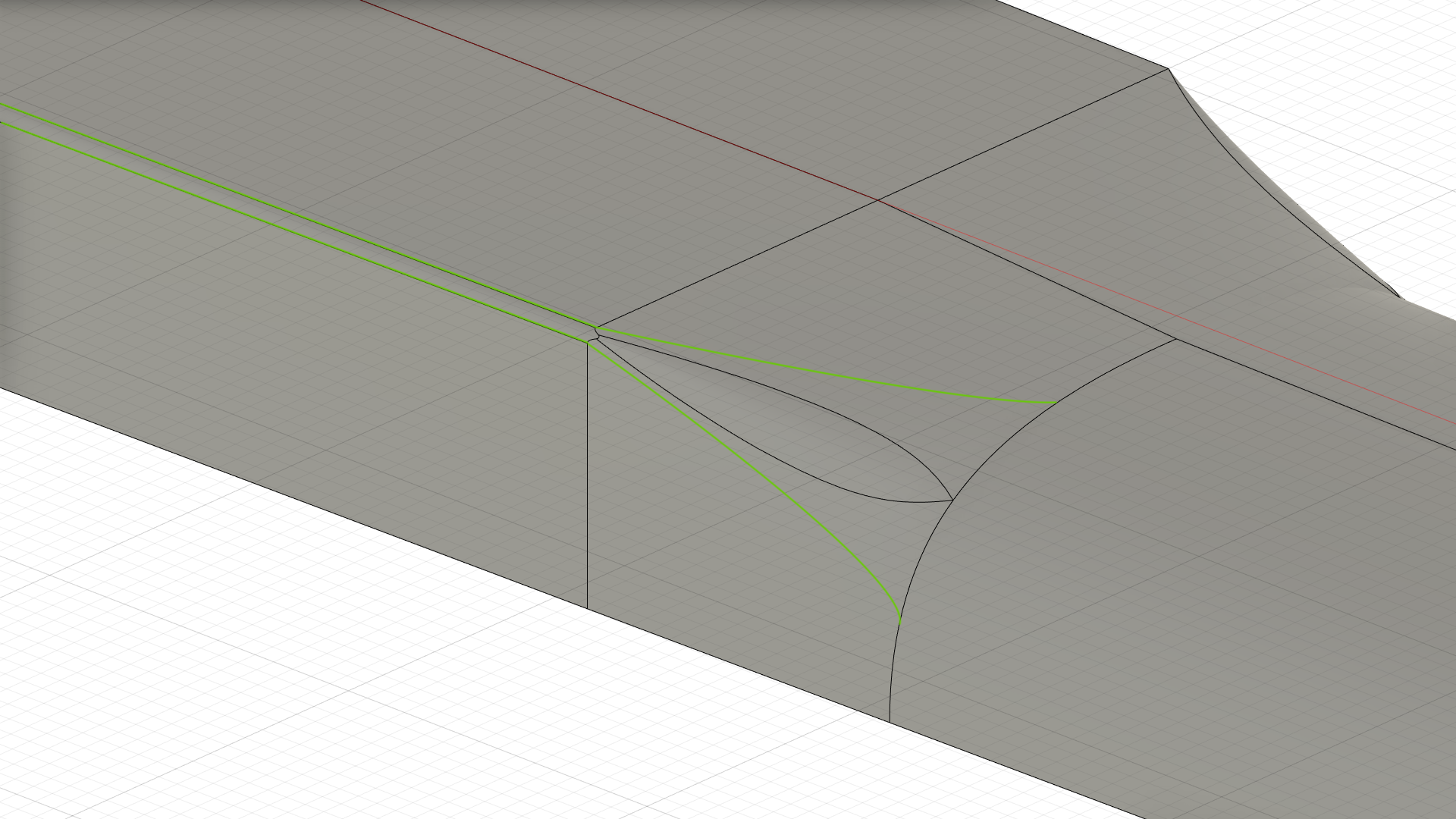
There is a problem area where an edge didn't stay inline on the top of the Heel.
oops, got lazy. when combining flat straight sections with curves in a single loft you have to be careful with your rails. (well, gotta be careful any way, but extra careful). The attached has a few added, hopefully it's better.
There are a bunch of purple lines in there and I don't really understand how you did that.
I get that you would use Loft and Rails but not how to get them in the right spots.
the purple lines are projections. in this case fusion added them automatically when I added the rails. The rails are constrained to be tangent to the edges of the helper body I lofted in as a surface. (the body named "helper"). The procedure was
-to start a new sketch, select any plane (I selected the xz origin plane) for the sketch plane
-make sure 3d sketching was turned checked on
-draw a 2 point fit point spline between the vertexes
-apply a tangent coincident between the spline and each edge (this is the point where the purple line will appear. fusion does that automatically. don't care for it, but oh well)
Also I am not able to move the curvature handles around to change the shape of the curves.
once a curve is off the sketch plane and out in 3d space, it can only be manipulated with the move command. messing with 3d splines is quirky, requires patience. select a tangent line endpoint, right click, select move from the marking menu. since there is a tangent constraint it will only move along a line, but you can shorten and lengthen it.
Here are some images I took of a real guitar neck I have
so you can better see the shapes.

ahh yes, and the rest of the story.
so we need to step back and take a slightly different run at this if you want that well defined edge. the current approach won't get there with out some modification.


