Community
- Forums Home
- >
- Civil 3D Community
- >
- Civil 3D Forum
- >
- Re: Transformation tab settings keep reverting back
Civil 3D Forum
Welcome to Autodesk’s Civil 3D Forums. Share your knowledge, ask questions, and explore popular AutoCAD Civil 3D topics.
Turn on suggestions
Auto-suggest helps you quickly narrow down your search results by suggesting possible matches as you type.
Reply
Topic Options
- Subscribe to RSS Feed
- Mark Topic as New
- Mark Topic as Read
- Float this Topic for Current User
- Bookmark
- Subscribe
- Printer Friendly Page
Message 1 of 20
12-17-2015
03:31 PM
- Mark as New
- Bookmark
- Subscribe
- Mute
- Subscribe to RSS Feed
- Permalink
- Report
12-17-2015
03:31 PM
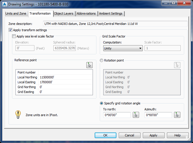
My files are in NAD83 (UTM83-12IF) and I am trying to label in a truncated coordinate systems using Grid Northing/Easting under the Drawing Settings: Transformation tab.
I enter my truncated coordinates into the Reference point area:
Local Northing: 11500000'
Local Easting: 1700000'
and it works great until save / re-open the file and it always reverts back to following settings:
Local Northing: 15073045.3484029'
Local Easting: 1640419.94750656'
Grid Northing: 41.5’
Grid Easting: -111’
Screenshot attached.
Any ideas or help is greatly appreciated
Solved! Go to Solution.
Solved by Pointdump. Go to Solution.
19 REPLIES 19
Message 2 of 20
12-17-2015
04:24 PM
- Mark as New
- Bookmark
- Subscribe
- Mute
- Subscribe to RSS Feed
- Permalink
- Report
12-17-2015
04:24 PM
AB,
OK, that's the "after". Please post a screen shot of "before". Since your Scale Factor is set to Unity, why do you want to transform your points? If you keep them in UTM, you can use Bing Live Maps for aerial images.
Dave
Dave Stoll
Las Vegas, Nevada
NVIDIA Quadro P5000 16GB
Windows 10 Pro 64 / Civil 3D 2024
Message 3 of 20
12-17-2015
05:13 PM
- Mark as New
- Bookmark
- Subscribe
- Mute
- Subscribe to RSS Feed
- Permalink
- Report
12-17-2015
05:13 PM
Hi Dave,
I am trying to label in truncated UTM (Northing -11,500,000’ Easting -1,700,000’ without any scale factor) while the data remains in UTM.
I have done this on another project where I could label in coordinate system A while working with the data in coordinate system B but this time I can’t figure out why the Transformation tab keeps reverting back once I save and refresh.
Transform Tab before.png attached.
Adam
Message 4 of 20
12-17-2015
05:28 PM
- Mark as New
- Bookmark
- Subscribe
- Mute
- Subscribe to RSS Feed
- Permalink
- Report
12-17-2015
05:28 PM
Adam,
Normally in your Grid Northing and Grid Easting you'd put in, say, 5000,5000. Or in your case something like 1150,1700. But I've not seen anyone use 0,0.
I'm guessing that C3D is freaking out over the 0,0 transformation and it's throwing up its hands and using the geomarker center point lats and longs to fill in the numbers. Not sure though.
Dave
Dave Stoll
Las Vegas, Nevada
NVIDIA Quadro P5000 16GB
Windows 10 Pro 64 / Civil 3D 2024
Message 5 of 20
12-18-2015
12:39 PM
- Mark as New
- Bookmark
- Subscribe
- Mute
- Subscribe to RSS Feed
- Permalink
- Report
12-18-2015
12:39 PM
As a test I opened up my previous project file which was done in C3D 2011 (and worked fine). I then saved as a new file using C3D 2015 and had the same result. The coordinates change/update upon save & refresh even though I did not change anything in the file. All I did was save as in 2015.
Message 6 of 20
12-18-2015
03:27 PM
- Mark as New
- Bookmark
- Subscribe
- Mute
- Subscribe to RSS Feed
- Permalink
- Report
12-18-2015
03:27 PM
Those grid numbers look like Lat & Long values. There is a known issue when you use the Map tools to assign a coordinate system to the drawing. If you use the GEOGRAPHICLOCATION command, or MAPCSASSIGN then it dumps values into the Transformation tab of the C3d settings. The problem is that it puts Lat - Long where there should be grid coords.
Steve
Please use the Accept as Solution or Kudo buttons when appropriate
Steve
Expert Elite Alumnus
Expert Elite Alumnus
Message 7 of 20
12-19-2015
12:16 AM
- Mark as New
- Bookmark
- Subscribe
- Mute
- Subscribe to RSS Feed
- Permalink
- Report
12-19-2015
12:16 AM
Adam,
Steve is right. I put these coords into the Geodetic Calculator:
Local Northing: 15073045.3484029'
Local Easting: 1640419.94750656'

And got this:
Latitude: N41° 29' 59.99999998"
Longitude: W111° 00' 00.00000000"
As a further test, I set the Coordinate System in one new drawing from the Map Workspace (MAPCSASSIGN) and one in the Civil Workspace (Drawing Settings). Same results either way:

Dave
Dave Stoll
Las Vegas, Nevada
NVIDIA Quadro P5000 16GB
Windows 10 Pro 64 / Civil 3D 2024
Message 8 of 20
12-21-2015
12:14 PM
- Mark as New
- Bookmark
- Subscribe
- Mute
- Subscribe to RSS Feed
- Permalink
- Report
12-21-2015
12:14 PM
Hi Steve, do you know of any way to fix this to get the result I am trying to achieve? i.e. working in UTM but have surface labels show Grid N/E
Message 9 of 20
12-21-2015
12:56 PM
- Mark as New
- Bookmark
- Subscribe
- Mute
- Subscribe to RSS Feed
- Permalink
- Report
12-21-2015
12:56 PM
Adam,
I'm completely not understanding what you're trying to do.
Questions:
1. Why not keep everything in UTM? Are you trying to match up UTM with existing Project Coords?
2. The Transformation Tab is meant to match up a Local point with a Grid point. Example: 11500000,1700000 with 5000,5000. Do you really want 11500000,1700000 to be translated to 0,0? If so, did you hit the "Apply" button? Nothing happens until you hit Apply.
3. Your Surface uses "Local" Points, not the Transformed "Grid" points. (Autodesk really needs to fix their terms.) Do you want your Surface to use the UTM points or the Project points? If Project, you'll need to Export the "Grid"(Translated) points to another drawing.
After Tranformation, the only thing that happens is that your point list shows two more columns, Grid Northing and Grid Easting:

Dave
Dave Stoll
Las Vegas, Nevada
NVIDIA Quadro P5000 16GB
Windows 10 Pro 64 / Civil 3D 2024
Message 10 of 20
12-21-2015
02:01 PM
- Mark as New
- Bookmark
- Subscribe
- Mute
- Subscribe to RSS Feed
- Permalink
- Report
12-21-2015
02:01 PM
Hi Dave,
I am working UTM but would like to have a surface label that can display both UTM and truncated UTM simultaneously.
In my surface spot elevation label style (screenshot 1 attached) I have:
UTM N = <[Surface Northing(P2|RN|AP|GC|U3|Sn|OF)]>
UTM E = <[Surface Easting(P2|RN|AP|GC|U3|Sn|OF)]>
GRID N = <[Surface Grid Northing(P2|RN|AP|GC|U3|Sn|OF)]>
GRID E =<[Surface Grid Easting(P2|RN|AP|GC|U3|Sn|OF)]>
I set the Local Northing to 11,500,000 and Local Easting to 1,700,000 to truncate the UTM coordinates (screenshot 2 attached).
My problem is it works fine until I hit save and my label changes/updates (screenshot 3 attached) because it is loosing what I entered in my Transformation tab.
Thank you very much for you help so far!
Adam
Message 11 of 20
12-21-2015
11:13 PM
- Mark as New
- Bookmark
- Subscribe
- Mute
- Subscribe to RSS Feed
- Permalink
- Report
12-21-2015
11:13 PM
Adam,
OK, I see now what you're doing. Ditch the Transformation Tab and get yourself a couple of shiny new Expressions for your Spot Elevation Labels:


Then put this in your Spot Elevation Label Contents:
UTM N = <[Surface Northing(P2|RN|AP|GC|UN|Sn|OF)]>
UTM E = <[Surface Easting(P2|RN|AP|GC|UN|Sn|OF)]>
Grid N = <[Truncate Northing(Uft|P2|RN|AP|GC|UN|Sn|OF)]>
Grid E = <[Truncate Easting(Uft|P2|RN|AP|GC|UN|Sn|OF)]>
Voila!

And I've got to know, how do you get that nice readable text in your Text Component Editor?
Dave
Dave Stoll
Las Vegas, Nevada
NVIDIA Quadro P5000 16GB
Windows 10 Pro 64 / Civil 3D 2024
Message 12 of 20
12-22-2015
06:04 AM
- Mark as New
- Bookmark
- Subscribe
- Mute
- Subscribe to RSS Feed
- Permalink
- Report
12-22-2015
06:04 AM
@Pointdump wrote:
And I've got to know, how do you get that nice readable text in your Text Component Editor?
Turn off Clear Type Text in Windows Display settings.
Message 13 of 20
12-22-2015
06:09 AM
- Mark as New
- Bookmark
- Subscribe
- Mute
- Subscribe to RSS Feed
- Permalink
- Report
12-22-2015
06:09 AM
Jeff,
Thanks. I discovered that this morning and it is definitely an improvement. But Adam also had Yellow Color for his text. How'd he do that?
Dave
Dave Stoll
Las Vegas, Nevada
NVIDIA Quadro P5000 16GB
Windows 10 Pro 64 / Civil 3D 2024
Message 14 of 20
12-22-2015
06:35 AM
- Mark as New
- Bookmark
- Subscribe
- Mute
- Subscribe to RSS Feed
- Permalink
- Report
Message 15 of 20
12-22-2015
07:10 AM
- Mark as New
- Bookmark
- Subscribe
- Mute
- Subscribe to RSS Feed
- Permalink
- Report
12-22-2015
07:10 AM
Thank you Jeff. I'm going to investigate that right now.
I've noticed that after turning off Clear Type Text in Windows, text in Notepad is harder to read. (I use Notepad to compose my posts to this Forum.)
Dave
Dave Stoll
Las Vegas, Nevada
NVIDIA Quadro P5000 16GB
Windows 10 Pro 64 / Civil 3D 2024
Message 16 of 20
12-22-2015
07:14 AM
- Mark as New
- Bookmark
- Subscribe
- Mute
- Subscribe to RSS Feed
- Permalink
- Report
12-22-2015
07:14 AM
Yes, the CTT definitely make everything else on my laptps and other LCD screens much sharper, at the cost of the TextComponentEditor for styles looking like crappola. So I leave CTT checked on and suffer with the styles issue since I spend far less time editing label styles than I do doing anything else in Windows.
Message 17 of 20
09-22-2016
06:23 PM
- Mark as New
- Bookmark
- Subscribe
- Mute
- Subscribe to RSS Feed
- Permalink
- Report
09-22-2016
06:23 PM
i have troubleshooted the problem and have found the solution, if, your problem is that the transformation tab settings in the grid nothing and easting keeps reverting back, or showing lat, long instead of the grid coordinates.
solution:
in the options menu, open and save tab, set file save as to autocad 2013 drawing (.dwg)
that's it. do not save the .dwg file if its not in 2013 dwg. the transfoemation will revert if not .dwg 2013. that was my problem before.
t.y.
Message 18 of 20
Anonymous
in reply to:
Anonymous
10-08-2019
07:59 AM
- Mark as New
- Bookmark
- Subscribe
- Mute
- Subscribe to RSS Feed
- Permalink
- Report
10-08-2019
07:59 AM
Gentlemen,
No disrespect but I think the point is being lost here. This transformation setting issue just started to occur with 2018. I have used transformation settings for at least 9 years now with no issue on previous versions. Using transformation settings is common practice with Oil and Gas facilities since the other disciplines and construction need to see plant (local grid) coordinates not UTM. This is a 2018 problem, I am inclined to believe that some toggle that was not in previous versions is now in 2018. IF anyone can help without questioning the who, what, or why we use transformation settings please come forward.
Message 19 of 20
10-08-2019
08:14 AM
- Mark as New
- Bookmark
- Subscribe
- Mute
- Subscribe to RSS Feed
- Permalink
- Report
10-08-2019
08:14 AM
You should probably start a new thread explaining your specific problem, since 2018 didn't exist in 2016.
Rick Jackson
Survey CAD Technician VI
Did you find this post helpful? Feel free to Like this post.
Did your question get successfully answered? Then click on the ACCEPT SOLUTION button.
Message 20 of 20
10-08-2019
08:21 AM
- Mark as New
- Bookmark
- Subscribe
- Mute
- Subscribe to RSS Feed
- Permalink
- Report
10-08-2019
08:21 AM
Apologies my IT people gave me the link to this thread didst realize that
it was for 2016 rather than 2018. However this problem is now happening to
me on 2018 when it never did before on previous versions, I am convinced it
is some dumb toggle Autodesk added to this version.
it was for 2016 rather than 2018. However this problem is now happening to
me on 2018 when it never did before on previous versions, I am convinced it
is some dumb toggle Autodesk added to this version.
Reply
Topic Options
- Subscribe to RSS Feed
- Mark Topic as New
- Mark Topic as Read
- Float this Topic for Current User
- Bookmark
- Subscribe
- Printer Friendly Page
Forums Links
Can't find what you're looking for? Ask the community or share your knowledge.
Post to forums

