Cross section view

Cross section view

alexandru.murariu1989
Advocate Advocate
2,733 Views
22 Replies
Message 1 of 23

Cross section view

alexandru.murariu1989
Advocate
Advocate

How can i get the same result like în this video.

https://youtu.be/ECIFoHop3dM


The a notate above the section and the band labels, where are eg ELEVATION, coridor ELEVATION and offset distance. I mean for example, for ETW to represent the eg ELEVATION, Project ELEVATION and offset, all for same Point.

Ty

0 Likes
Accepted solutions (1)
2,734 Views
22 Replies
Replies (22)
Message 2 of 23

Civil3DReminders_com
Mentor
Mentor

This should show the steps: https://www.youtube.com/watch?v=o4TATd_RW9o 

Civil Reminders
http://blog.civil3dreminders.com/
http://www.CivilReminders.com/
Alumni
0 Likes
Message 3 of 23

I was partially Succesfull, only for finished ELEVATION and offset. I don t know how to represent the ground ELEVATION... 

0 Likes
Message 4 of 23

And how can i represent în cross section view property limit? I have a polyline represent the limit.. 

0 Likes
Message 5 of 23

ilia.borisov
Collaborator
Collaborator
If I understand right to show ground elevation you need to change surface that represent specific label from Section View Properties>Band tab and then Section1 or Section2
0 Likes
Message 6 of 23

alexandru.murariu1989
Advocate
Advocate

I represent the finish ground and offset with Code set style. The band is blank, doesn t show data. Only for existing ground i used the band... 

0 Likes
Message 7 of 23

ilia.borisov
Collaborator
Collaborator
Ok where do you want to represent ground elevation
0 Likes
Message 8 of 23

alexandru.murariu1989
Advocate
Advocate

În same location like finishgr and offset 

0 Likes
Message 9 of 23

ilia.borisov
Collaborator
Collaborator
Some image would be very helpful
0 Likes
Message 11 of 23

alexandru.murariu1989
Advocate
Advocate

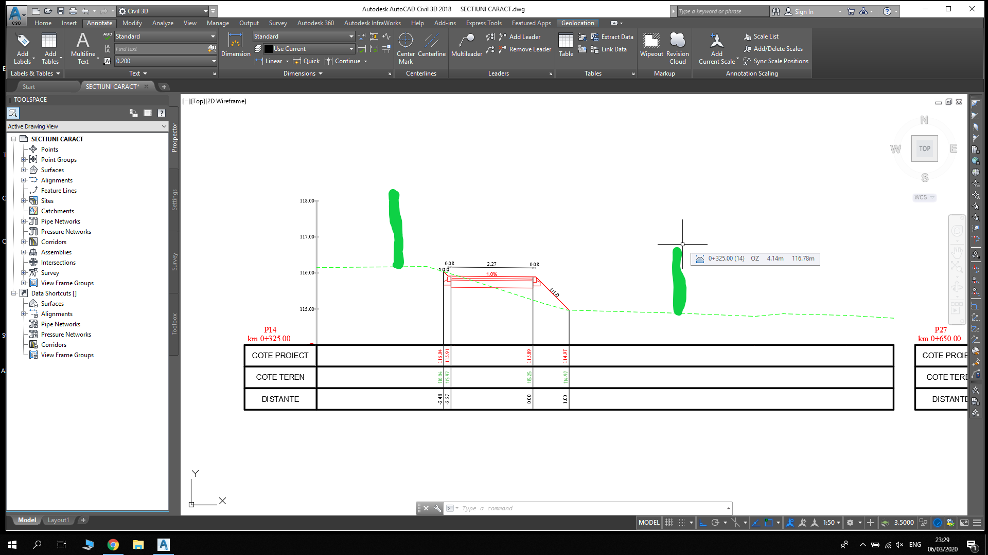
i attached 2 photo, as u can see in bands that is the result, only offset and FG are where i want, and EG is on major cause i can t figure how to represent in same points..

And i draw something, how can i represent limit propretry and road alignment in section view?.

i put the dwg format, maybe some1 can help me.. i spent 2days and i don t know ho to do it... ty !

0 Likes
Message 12 of 23

M_Obradovic
Collaborator
Collaborator

Hi,

i import my band set in your cross section as you can see in attached drawing. But if you want to work correct corridor section must be on sample line in order to surface triangle create on sample line. Also delete all triangles outside boundary line.( And just change the language 😄 )


Cheers Milos....

0 Likes
Message 13 of 23

alexandru.murariu1989
Advocate
Advocate

ty ! works fine only i have some errors

how can i fix this? 

0 Likes
Message 14 of 23

M_Obradovic
Collaborator
Collaborator

This errors depence of FG surface. Your FG is not create until boundary of corridor. you have more triangles outside as you can see on attached photo. You can delete triangles from surface and will work ok.Becouse FG surface control Band set.

0 Likes
Message 15 of 23

alexandru.murariu1989
Advocate
Advocate

Hmm. I need to delete all triangles? How can i know wich one i need to delete? If i delete after daylight future line în section Will not appear the elevation

0 Likes
Message 16 of 23

M_Obradovic
Collaborator
Collaborator
Accepted solution

It is not necessary to delete manually each triangles. After creation corridor create Top Surface from top links of your corridor and program will recognize where is the boundary. If still you have more triangles behind boundary go to surface properties >definition tab> build> maximum triangle length and set to for example 10m. 

0 Likes
Message 17 of 23

alexandru.murariu1989
Advocate
Advocate

ty sir for ur help! works fine >D

Now i have one problem. how to project a fence (property limit) on section view. I have a polyline wich represent the property limit, any idea how to do it?

0 Likes
Message 18 of 23

M_Obradovic
Collaborator
Collaborator

As I understand good you have polyline what represent fense in model space. You want to show this polyline in section view with some sign or point ( or whatever else). If you have any photo will be good to understand exactly what you want.

0 Likes
Message 19 of 23

alexandru.murariu1989
Advocate
Advocate

in  plan photo u can see a green line wich represent the proprety limit(fence), in cros section photo i draw a green line, how i want to represent the fence...it s posible?


in 1st post in that movie u can see on both side how is represent...

0 Likes
Message 20 of 23

M_Obradovic
Collaborator
Collaborator

Yes it is possible. Create assembly just with surface link and assign left and right point code ( for example "fense"). start to create corridor and use offset target your polyline.  When you create corridor import coridor in section view and control left and right point code by Code set stile. 

0 Likes