Community
AutoCAD Plant 3D Forum
Welcome to Autodesk’s AutoCAD Plant 3D Forums. Share your knowledge, ask questions, and explore popular AutoCAD Plant 3D topics.
Turn on suggestions
Auto-suggest helps you quickly narrow down your search results by suggesting possible matches as you type.
Reply
Topic Options
- Subscribe to RSS Feed
- Mark Topic as New
- Mark Topic as Read
- Float this Topic for Current User
- Bookmark
- Subscribe
- Printer Friendly Page
Message 1 of 3
Anonymous
692 Views, 2 Replies
08-06-2018
09:54 PM
- Mark as New
- Bookmark
- Subscribe
- Mute
- Subscribe to RSS Feed
- Permalink
- Report
08-06-2018
09:54 PM
ortho generation
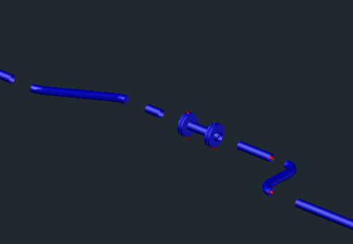
Here is a sample of my model. (see model.png)
I have created several iso drawings of my model.
for production purpose, the workers told me to give an ortho view of each iso drawing.
Finding no way, I manually separated my model according to the isos. (see model separation.png)
and then created ortho drawing. (see ortho.png)
Would any of you tell me a way how i can do this in a more automatic way? such as how i can separate my model according the generated isos, or automatic ortho generation according to iso. or even how can i tag each separated parts (according to iso drawing no) in ortho automatically ? I will appreciate any kind of technique/solution that will help me do this work more easily
2 REPLIES 2
Message 2 of 3
08-07-2018
11:48 PM
- Mark as New
- Bookmark
- Subscribe
- Mute
- Subscribe to RSS Feed
- Permalink
- Report
08-07-2018
11:48 PM
Dear @Anonymous,
the Ortho function in Plant 3D is not intended for ISO creation as in your case.
You will find your problem only by manual means or you know someone who can program this task as an add-on.
-
If my reply was helpful, please give a "Kudo" or click the "Accept as Solution" button below (or both).
If my reply was helpful, please give a "Kudo" or click the "Accept as Solution" button below (or both).
Hartmut Eger
Senior Engineer
Anlagenplanung + Elektotechnik
XING | LinkedIn
Message 3 of 3
05-14-2021
09:13 AM
- Mark as New
- Bookmark
- Subscribe
- Mute
- Subscribe to RSS Feed
- Permalink
- Report
05-14-2021
09:13 AM
[Note: this post is old. You are probably already done with this project. However, I'm posting so other people can see my thoughts in the future, should they have the same issue.]
I couldn't imagine any easy method to do what you want to do. As Hartmut said, orthos are not intended for this.
Any of the solutions I propose below will take time to set up. Experiment to see if they work before implementing them. Depending on the size of your project, they might cost you time instead.
Using layers might help, especially if most of your isos are broken up by line number. If you have to update the drawing repeatedly, you could add a custom "Iso dwg number" property for piping components (Project Setup > Plant 3D DWG Settings > Plant 3D class definitions > Piping and Equipment > Pipe Run Component; "Add..." button). Since iso drawings are downstream from the project, I don't believe you could make any kind of parametric link for what iso drawing a pipe appears on to be sent back into the model. Therefore, you'd have to keep this custom property updated whenever you change iso drawing numbers.
To automatically space components out, I think you'd have to adjust the project spec so that each item's node is spaced out from its geometry. This might be a piping spec item or it could be something in the connection rules. Alternatively, you could specify that anytime anything connects in the 3D model, plant needs to automatically add an invisible component (similar to how a spec can require backup rings or spaces to be automatically added to a flanged connection when working with certain materials). The component would have nodes spaced out to whatever gap size you want, while it shows no geometry. The problem with either solution is you'd have to find some way to preserve the original geometry (otherwise a 6' stretch of pipe becomes a 4' stretch of pipe with 1' gaps on either side). How you can do this, I don't know.
To make the ortho tag automatic, you need some kind of property for the iso drawing number as mentioned above. Using that, you can create a new ortho tag. Go to the same place in Project Setup [the Pipe Run Component area] and use the "Ortho Annotation Setup" in the lower right corner to Add Annotation... and Edit Block..., assigning your custom property to the tag you want. This blog post explains something vaguely similar to what you want, except what you want to do in this instance is simpler.
Ultimately, it sounds like a headache. I'd badger your construction team until they let you get some kind of compromise, such as creating ortho views of various sections of the plant. They're asking a lot from you, even if they don't realize it.
P.S. One other solution entirely could be to use an iso drawing and make it look like an ortho. If you set up your iso style right, you can use insulation to imitate pipe thickness, making the centerlines dashed and hiding dimensions. You could make the Bill of Materials use part number and your custom iso drawing number property, change the iso tagging to automatically use your custom property (which takes some effort), add an Iso Message to each piping component with the drawing number called out, or manually tag each component in the "ortho" drawing. This might be the easiest solution. It won't look official, but if all they're fishing for is a more intuitive representation of iso drawings, it would work.
Reply
Topic Options
- Subscribe to RSS Feed
- Mark Topic as New
- Mark Topic as Read
- Float this Topic for Current User
- Bookmark
- Subscribe
- Printer Friendly Page
Forums Links
Can't find what you're looking for? Ask the community or share your knowledge.
Post to forums
