Community
- Forums Home
- >
- AutoCAD Plant 3D Community
- >
- AutoCAD Plant 3D Forum
- >
- Elbow rotated in isometric and lost proper connection
AutoCAD Plant 3D Forum
Welcome to Autodesk’s AutoCAD Plant 3D Forums. Share your knowledge, ask questions, and explore popular AutoCAD Plant 3D topics.
Turn on suggestions
Auto-suggest helps you quickly narrow down your search results by suggesting possible matches as you type.
Elbow rotated in isometric and lost proper connection
6 REPLIES 6
SOLVED
Reply
Topic Options
- Subscribe to RSS Feed
- Mark Topic as New
- Mark Topic as Read
- Float this Topic for Current User
- Bookmark
- Subscribe
- Printer Friendly Page
Message 1 of 7
05-12-2022
10:29 AM
- Mark as New
- Bookmark
- Subscribe
- Mute
- Subscribe to RSS Feed
- Permalink
- Report
05-12-2022
10:29 AM
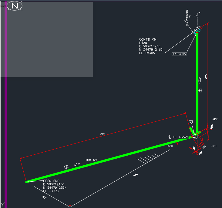
When I create an elbow rolled, the elbow will be rotated in isometric and lost the connection making the isometric completely useless. I am not sure if there is problem in my model or any setting, but I tried different way of modeling. This happens also when I model it even without rolled elbow and just to select a direction not aligned with X or Y axis for the pipe, in this example for horizontal pipe which is not aligned with X Y axis. I appreciate anyone can help.

Solved! Go to Solution.
Solved by Mj_Dan. Go to Solution.
6 REPLIES 6
Message 2 of 7
05-15-2022
09:56 AM
- Mark as New
- Bookmark
- Subscribe
- Mute
- Subscribe to RSS Feed
- Permalink
- Report
Message 3 of 7
05-17-2022
02:05 AM
- Mark as New
- Bookmark
- Subscribe
- Mute
- Subscribe to RSS Feed
- Permalink
- Report
05-17-2022
02:05 AM
@hamid.TCAD check the coordinates of your model, they must be very far from the origin (0,0). Also, try to model your plant using the WCS.
To resolve this, move your model closer to 0,0. Now, to get the accurate coordinates in your isometrics, go to project setup, Iso Style Default Setting to apply the offset value to your new coordinates
This post I made on the same issue might help Isometric Issues: Elbow Disconnecting

Message 4 of 7
05-17-2022
08:49 AM
- Mark as New
- Bookmark
- Subscribe
- Mute
- Subscribe to RSS Feed
- Permalink
- Report
Message 5 of 7
05-17-2022
10:30 AM
- Mark as New
- Bookmark
- Subscribe
- Mute
- Subscribe to RSS Feed
- Permalink
- Report
05-17-2022
10:30 AM
Now I see all connections in the model gone. I have to select one by one and run "Connected to Adjacent". They are not huge numbers, but for some of them, isometrics have been created and issued to the client that makes me a bit concerned. Is there any way that we can keep all parts connected when we move them?

Message 6 of 7
02-10-2023
10:00 AM
- Mark as New
- Bookmark
- Subscribe
- Mute
- Subscribe to RSS Feed
- Permalink
- Report
02-10-2023
10:00 AM
The solution provided here, although effective in its own way, I don't think reflects the reality of the reason many projects are oriented significant distances from the origin. We have several mining customers that have sites spanning distances of dozens of kilometers, each with 3D model turn-over requirements that drive us to model in coordination with each customers defined plant coordinate system, which often has a singular origin located at a convenient UTM intersection. Generally this doesn't usually cause many issues. In fact, we have a current project where we've integrated customer supplied Autocad and Navisworks models, inserted our own laser scan data using Recap, incorporated piping, structural, electrical and equipment models all together, all centered around a point over 50km from the origin, with project units in millimeters. In this entire project, the only issue we've detected as a result of this offset from origin is the rolled elbow that can't calculate its three points correctly (even a 16" elbow, so we're not talking about 1/4" tubing here where the coordinates are that much closer together), resulting in a disconnected looking isometric. Perhaps Autodesk can have someone take another look at this issue to see if the isometric functions for displaying these elbows can be revisited to accommodate users requirements to meet their customers needs. Simply offsetting the plant opens an entire other can of worms for which I don't think we have much of an appetite.
Message 7 of 7
07-18-2024
02:18 AM
- Mark as New
- Bookmark
- Subscribe
- Mute
- Subscribe to RSS Feed
- Permalink
- Report
Reply
Topic Options
- Subscribe to RSS Feed
- Mark Topic as New
- Mark Topic as Read
- Float this Topic for Current User
- Bookmark
- Subscribe
- Printer Friendly Page
Forums Links
Can't find what you're looking for? Ask the community or share your knowledge.
Post to forums

