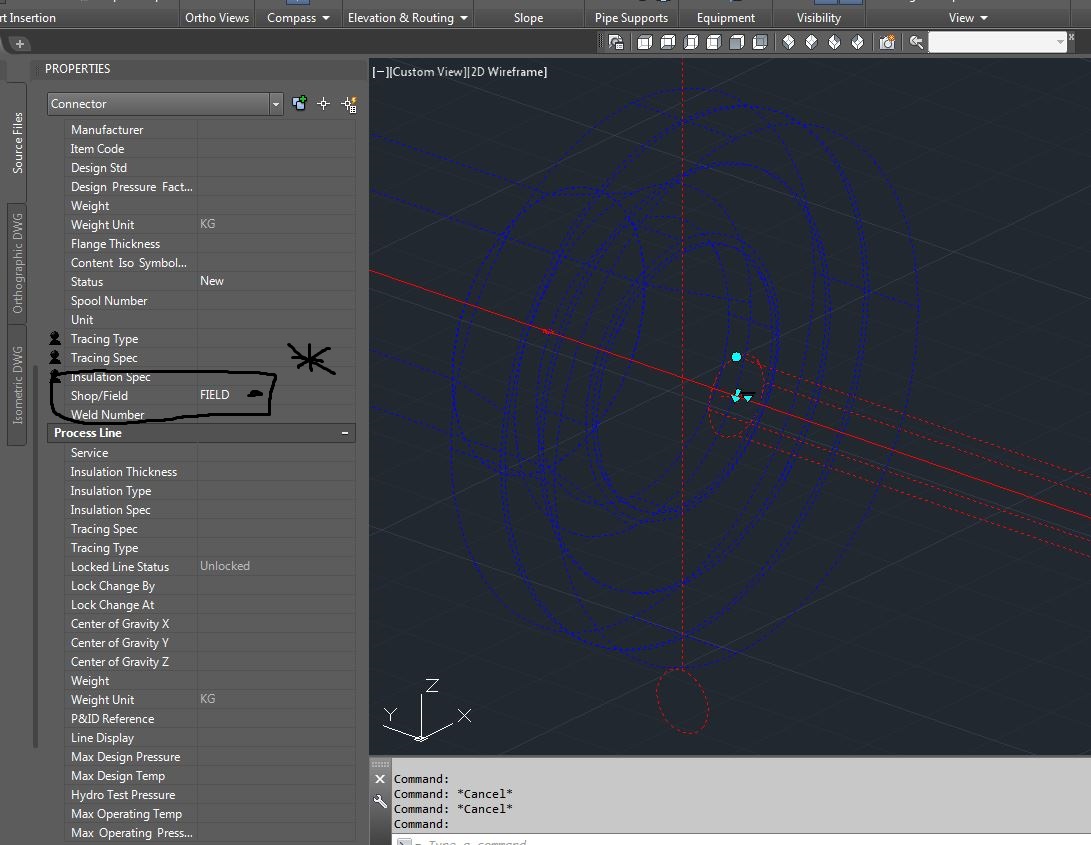
Blind Flange - tap weld missing from Iso

Blind Flange - tap weld missing from Iso

MOLGRAND
Advocate Advocate
1,455 Views
4 Replies
Message 1 of 5

Blind Flange - tap weld missing from Iso

MOLGRAND
Advocate
Advocate

Hi,

I have a slight irritation in that when adding a pipe run into the back of the blind flange, although it models well & there are no issues, but when I run the iso the tap weld doesn't show up on the iso. The only time it does appear iso is when you change the weld from a shop to field weld, then it does appear on the iso. When a SOL or WOL is added to the flange instead of the pipe then weld does appear on the iso correctly - so is the pipe connection weld a bug or can anyone advise a solution.

Regards

Gary Randall

0 Likes
1,456 Views
4 Replies
Replies (4)
Message 2 of 5

h_eger
Mentor
Mentor

Dear @MOLGRAND,


unfortunately I can not repruduce your mistake.


2018-09-28_11-34-26.jpg

-

If my reply was helpful, please give a "Kudo" or click the "Accept as Solution" button below (or both).

Hartmut Eger
Senior Engineer
Anlagenplanung + Elektotechnik
XING | LinkedIn

EESignature


0 Likes
Message 3 of 5

MOLGRAND
Advocate
Advocate

Hi,

Thanks for coming back to me.

I am running P3D - 2018, what version did you generate the Iso on? I have reloaded 2018 again today from scratch to make sure I didn't have any software issues & I just created a new project metric-metric so its an out of the box set-up with no changes & used the final Iso template & I still get the same error result!

Regards

Gary

0 Likes
Message 4 of 5

h_eger
Mentor
Mentor

Dear @MOLGRAND,


also in 2018 the action is successful

2018-09-28_12-29-31.jpg

-

If my reply was helpful, please give a "Kudo" or click the "Accept as Solution" button below (or both).

Hartmut Eger
Senior Engineer
Anlagenplanung + Elektotechnik
XING | LinkedIn

EESignature


0 Likes
Message 5 of 5

Bernd.Gerstenberger
Autodesk Support
Autodesk Support

Dear Molgrand,


the reason therefore is in most cases configuration. Please, can you send us the following files:

  1. Small sample model drawing
  2. Zipped iso style folder
  3. From <project folder>\Isometric the following files:
    1. IsoSymbolStyles.dwg
    2. IsoSkeyAcadBlockMap.xml
  4. DefaultConnectorsConfig.xml from project folder

Best regards


Bernd G.

Senior Product Support Specialist


0 Likes