AutoCAD Electrical Forum
Welcome to Autodesk’s AutoCAD Electrical Forums. Share your knowledge, ask questions, and explore popular AutoCAD Electrical topics.
cancel
Showing results for 
Show  only  | Search instead for 
Did you mean: 

Creating a 4 pin feed through terminal block

9 REPLIES 9
SOLVED
Reply
Message 1 of 10
Anonymous
2781 Views, 9 Replies

Creating a 4 pin feed through terminal block

Need a little help in setting up AB 1492-L3Q.  It has 2 sets of connectors on both sides and all the terminal points are connected internally to each other.


Does anybody out there have a similar example?  Thanks for any help that anyone can provide.

9 REPLIES 9
Message 2 of 10
dougmcalexander
in reply to: Anonymous

Are you looking for a schematic terminal symbol, or footprint symbol? 


The schematic terminal symbols that come with the software include 4 contact points, so there is really no need for a special terminal.  See below:


Schematic Terminal Symbol showing 4 wire connections.png


If you wish to show each wire connection as a separate terminal symbol in 4 separate places throughout the schematic, you can connect the individual symbols with a wire type layer called JUMPER.  Bear in mind though that the Terminal Strip Editor will see this as 4 separate terminals and will therefore try to insert 4 separate footprints.  I posted an idea to the idea station to allow the same terminal be shown multiple times in a project and marked as a duplicate.  You can vote for this idea at:  https://forums.autodesk.com/t5/autocad-electrical-ideas/allow-the-same-schematic-terminal-symbol-to-...


Another option you can use to document the internal jumper is to use the Edit Jumper utility to create an invisible link between the separate terminal symbols.


The simplest way to handle your scenario is to connect wires to the top, bottom, left, and right wire connections of one schematic terminal symbol.  Use source/destination arrows if wires must continue to another drawing.  This workflow will avoid the confusion I mentioned earlier, when the Terminal Strip Editor interprets each schematic terminal symbol as a separate physical terminal block.


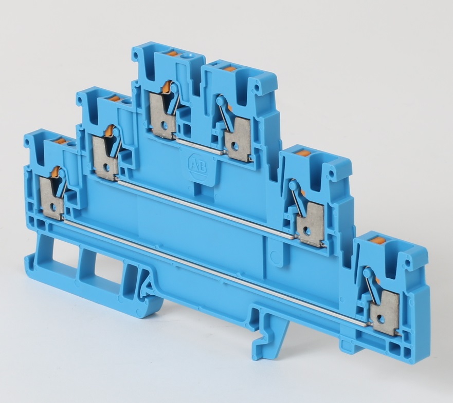
Yet another thing you can do is edit the record for the 1492-L3Q in the Catalog Database and convert it to a 4-level terminal. You can even define the jumper between all 4 "levels", as shown below.


Multilevel Terminal Block definition in Catalog Database.png


The software will then allow you to insert 4 separate schematic terminal symbols and assign each one to a different level of the same physical terminal.


If a footprint is what you need for the 1492-L3Q, there is a simple stock footprint included with the software.  The block is named ABTBK090.DWG, located in the Panel\AB\C:\Users\Public\Documents\Autodesk\Acade 2019\Libs\panel\AB\TRMS-TERMINAL BLOCKS folder.  You will see this footprint block when you open the Terminal Strip Editor to prepare to insert the graphical terminal strip into your panel layout, as shown in the screen capture below.


AB_1492_L3Q_FOOTPRINT.png


Doug McAlexander


Design Engineer/Consultant/Instructor/Mentor specializing in AutoCAD Electrical training and implementation support

Phone and Web-based Support Plans Available

Phone: (770) 841-8009

www.linkedin.com/in/doug-mcalexander-1a77623


Please Accept as Solution if I helped you. Likes are also much appreciated.
Message 3 of 10
Anonymous
in reply to: dougmcalexander

I guess I need to be a little bit clearer in my question. I made some assumptions that don't seem to be working.


1- See attached Terminal Block Properties.  I assumed that once I put the internal jumpers across all 4 levels that I would need to  insert 4 terminals and then associate them by using the pick or add modify.  I would have 4 terminal points on my schematic but only using one terminal block.  Based on what I have seen, it is best to insert one terminal block symbol with 8 wires (2 per terminal, 4 terminals per block) and just bring the wires to that terminal block symbol.  I guess that I really do not understand the associations?


2 - Internal and External connections.  Here is another assumption that I made.  I assumed that these connections pertained to the internal terminal block connections.  The external would be the bar that would connect terminal blocks.  Example - power or common terminals.  Use jumpers to go across.  Thought this would be an external connection.  Would this be an internal connection?  External connections go to something that are not in this panel. Example - panel to field wiring.


I have more questions but these are the main ones.  Answering these will help with the others (or at least I think they should)


Thanks


Message 4 of 10
dougmcalexander
in reply to: Anonymous

From what you describe, I think your best approach might be to edit the record for the part number and designate it as a 4 level terminal.  Then you can insert 4 terminal symbols and assign each as one of the 4 levels.  The level assignment can be made easily in the Terminal Strip Editor.  Connect the terminal symbols to one another on the schematic with a wire type named JUMPER.  Since the terminal had an internal jumper built in to do not need to use the Edit Jumper utility to assign a part number for the jumper.


Internal and external refer to where the wires connecting to the terminal come from, another device inside the enclosure or a device outside of the enclosure.  You will also see this depicted in the Terminal Strip Editor.  You can also make the internal or external assignments in TSE.  I find it easier to create multi-level associations and internal/external assignments in TSE.


Doug McAlexander


Design Engineer/Consultant/Instructor/Mentor specializing in AutoCAD Electrical training and implementation support

Phone and Web-based Support Plans Available

Phone: (770) 841-8009

www.linkedin.com/in/doug-mcalexander-1a77623


Please Accept as Solution if I helped you. Likes are also much appreciated.
Message 5 of 10
Anonymous
in reply to: dougmcalexander

Thanks for your help.  Will give it a try and go from there.

Message 6 of 10
Anonymous
in reply to: Anonymous

Using this circuit as an example

mdeckerKSAC2_0-1618249642759.png


If I set the wires per connection to one.

mdeckerKSAC2_1-1618249642768.png


I get an extra terminal that messes up the footprint but the tab layout looks readable (besides the extra terminal)

mdeckerKSAC2_2-1618249642774.png


mdeckerKSAC2_3-1618249642778.png


However, if I set the wires per connection to 2

mdeckerKSAC2_4-1618249642784.png


I do not get the extra terminal, but the table is rather confusing as it has 2 lines per termination point.

mdeckerKSAC2_5-1618249642788.png


mdeckerKSAC2_6-1618249642790.png


Message 7 of 10
jseefdrumr
in reply to: Anonymous

Are there four terminal symbols in the schematic? We can only see two.


Are the terminals in the schematic associated with the Associate Terminal tool? They should be.


Also, the phrase 'wires per connection' should probably really say 'wires per level'. ACADE doesn't know how many screws/connections are on the terminal, just how many levels it has. A standard feed-through terminal always accepts two wires per level. Where I work, we often use double ferrules on terminals, so I have to set my 'wires per connection' to be 4 because that's how many wires I could potentially have on a level (two wires per terminal screw).


As far as the grid showing an extra line, I guess that comes down to what you're used to seeing. My grids always look like yours and I don't find them confusing.


Jim Seefeldt
Electrical Engineering Technician


Message 8 of 10
Anonymous
in reply to: Anonymous

Yes only 2 terminals shown but its setup like a 4 pole terminal block as shown above in this forum string.

Message 9 of 10
Icemanau
in reply to: Anonymous

I think the problem here is a matter of terminology.


Looking up the assigned part number (AB 1492-L4Q-B), it is a SINGLE level terminal with 2 spring connections per side.

See This Data Sheet - https://configurator.rockwellautomation.com/api/Doc/1492_L4_L4T_L4Q_Spec.pdf


Here is a photo of a Multi Level terminal with 1 spring connection per side for each level.


You can see the difference between the two right away.


Multi Level terminals come in all sorts of internal connections.

Feed through - Isolated levels as per the photo

Feed through - Linked levels

Feed through - Isolated with LED

and so on.


So for your example strips using the single level block, everything is correct.


For a multi level block, you would insert each level as a separate terminal and then Associate them using the Terminal Sub Menu from the radial menu or the TSE. Note that to do so, you must have assigned a part number for a terminal that has multiple levels set.


Regards Brad

>

Brad Coleman, Electrical Draftsman
Did you find this post helpful? Feel free to Like this post.
Did your question get successfully answered? Then click on the ACCEPT SOLUTION button.

EESignature

Message 10 of 10

I like how easy it is to manage a 4 level terminal however I am not overly fond of how the jumper chart lays out.  Using this approach, is it possible to have the jumper chart only show the jumpered terminals (rather than all signals)?  

(i.e. in my attached screenshot, I only want to show three items in the jumper chart along with the jumpers, not all 10 signals).

Can't find what you're looking for? Ask the community or share your knowledge.

Post to forums  

Technology Administrators


AutoCAD Beta