Orthotropic material orientation

Orthotropic material orientation

Anonymous
Not applicable
1,905 Views
10 Replies
Message 1 of 11

Orthotropic material orientation

Anonymous
Not applicable

Hello people.

It appears that when using brick orthotropic elements the only way to orient material  axis  is by prescribing a fixed  set of directions (common to all the elements in the part).


Since I need to model a roughly cylindrical body whose material axis coincide with the cylindrical coordinates covariant vectors that option (fixed axis) does not work for me.


Is there a workaround ? May be using the full anisotropic material model with direction prescribed in the moldflow format (without using moldflow)?


Reply
Reply
0 Likes
Accepted solutions (1)
1,906 Views
10 Replies
Replies (10)
Message 2 of 11

John_Holtz
Autodesk Support
Autodesk Support
Accepted solution

Hi eulerl. Welcome to the Sim Mech forum.


The Moldflow idea is an interesting one, but you would need to create Moldflow results because the Sim Mech analysis reads the Moldflow results to get the orientation (as well as the material properties).


The simplest method is to split the model into multiple parts so that you can define an orientation for each section.


A more complex solution would be to edit the databases and

  • define multiple material orientations, such as maybe every 15 degrees. (done in model.dbf)
  • re-assign the material identification (MAT_ID) for each element (done in elements.dbf) based on the position of the element (based on the coordinates in nodes.dbf). See the attached image.
  • run the analysis from a command prompt.

This type of solution would best be done with a program but could be done manually in Excel. Anyone interested in creating such a program?


Be sure to check the "Ideas" page to add your suggestion or vote for an existing one. (I did a quick search and found this suggestion which is for thermal analysis. There could be existing ideas for your suggestion that I did not come across.)


______________________________________________________________

If my post answers your question, please click the "Accept as Solution" button. This helps everyone find answers more quickly!


John Holtz, P.E.

Global Product Support
Autodesk, Inc.


If not provided, indicate the version of Inventor Nastran you are using.
If the issue is related to a model, attach the model! See What files to provide when the model is needed.
Reply
Reply
0 Likes
Message 3 of 11

Anonymous
Not applicable

Thank you John, I will try to edit the DB because it appears as the more flexible solution, also for future projects.

Reply
Reply
0 Likes
Message 4 of 11

Anonymous
Not applicable


Hi John, 

after 3 days of hard work I solved the problem following the "complex solution" you suggested.


I wrote a small C++ program to read and write the database (model and element tables) using the functions contained in the "agsdb_ar.dll" library.

In the last Algor distribution I have (may be a 2010 version) I found both the header file "agsdb_ar.h" and the static library interface "agsdb_ar.lib" that worked fine with the dll libraries of the Autodesk Mechanical Simulation 2017( Unfortunately it appears that the Autodesk distributions do not contain the header and the static lib file)


Since in my model each part is made by bricks whose orthotropic material axis are aligned with the local directors of a cylindical system of coordinates (CSoC), I associated to each part a different system of coordinates and the engineering coefficients defining the orthotropic elastic matrix.


Than for each CSoC  I inserted  into the model.dbf file, 40 new anisotropic materials whose Cij represent the elastic matrix with respect to the  global X,Y,Z directions of the orthotropic material whose axis are rotated by  theta= j* 2Pi/40, for j=0,...,39,  with respect to the z direction of the CSoC.


Finally I iterated over the elements, skipping those elements whose part was not associated with a CSoC, calculating the mean (Xm,Ym,Zm) of the element nodal coordinates and the cylindical coordinate theta of that point. From theta I obtained the ID of the material and updated the mat_id field in the element table.


All worked fine but I have some questions


1)

When I create a new anisotropic material for an elastic linear analysis, apart from the

"Material(n).Linear.Piezo.Cij"

"Material(n).General.Model"

and

"Material(n)..General.Density.Mass",

are there other  mandatory records to be inserted into the database?


Is there a comprehensive documentation of the model.dbf  table ?
 
 
2) executing the analysis manually I experienced an issue.  ssap0.exe works fine until it calls the mknso routine (stress calculation). mknso stops calculations after the first 7 parts. This happens also with models generated by Autodesk simulation 2017 (not processed by my program) .
 
Because I assume that also  launching the analysis from the Autodesk simulation 2017 IDE  calls ssap0, but in this case all the group stresses are calculated, whats the problem? (I run simulations on windows 10)


Reply
Reply
0 Likes
Message 5 of 11

AstroJohnPE
Advisor
Advisor

Hi,


I'm glad to read that it got your program written. That is impressive!


I'm sure there are a few details that I did not think of in my original post which you have probably uncovered. So to make sure we are on the same page, here is my understanding of what you did:

  1. Let's assume that your model has 1 part with anisotropic materials (or for other readers, it could be orthotropic).
  2. You create 40 different orientation records in model.dbf for part 1 Mat_Axis(n) to approximate the cylindrical coordinate system.  (mentioned in my original post)
  3. You copy the material properties for material 1 to create 39 new materials so that changing the "MAT_ID" for each element has  material properties (not mentioned in my original post Smiley Sad) In other words, the material properties for all elements are the same; only the orientation of the elements are different. But since changing the "MAT_ID" says that the element has "different" material properties, you need to copy the material property records.
  4. Based on the position of each element in part 1 relative to the cylindrical coordinate system, you change the "MAT_ID" to the appropriate variable.

Is that correct? It gets trickier if the model has other parts since you do not want to overwrite the material properties for the real parts 2 through 40 with the duplicate materials 2 through 40 for the anisotropic/orthotropic materials for the cylindrical system.


Now to your questions.

1) I do not know which material property records need to be copied. Probably the records with the source library and units are not used by solver and do not need to be copied. Now that I think of it, probably only the records that correspond to the values that you enter through the user interface are the only ones that need to be copied to 2 through 40.


As far as I know, there is no comprehensive list of model database variables, but I will check.


2) Can you clarify what type of model running through Sim Mech works and what does not? Your first paragraph suggests that a model with more than 7 anisotropic parts will fail in the stress calculation (MKNSO), but your second paragraph suggests that some type of model works okay.


I will try a few test models when I get a chance.

Reply
Reply
0 Likes
Message 6 of 11

Anonymous
Not applicable

Hi John, 

You are almost right  in your understanding of my program. 

 
To be more precise, my model is made by 11 parts. Parts 1 to 7 are orthotropic with material axis parallel to the local  directors of a cylindrical coordinate system ( a different one for each part) and need a special treatment. Parts 8 to 11 are orthotropic, too but the material axes are parallel to the global system of coordinates and thus they do not need further manipulation.
The original  model was generated by the Autodesk mech sym 2017 IDE, with materials 1-7 of anisotropic type (and casual elastic coefficients)  while for materials 8-11 the real coefficients were prescribed.
 
 
In the c++ program, I  defined 7 cylindrical systems of coordinates, one for each part 1-7, and for every system I inserted in model.dbf 40 new materials numbered with progressive ID starting from the last  material already present (11) plus one (12) to avoid numbering overlapping. The original materials 1 to 11 remained in the table but materials 1-7  were not used.
The 7* 40  new materials are of anisotropic type and, at least at my best knowledge, there is not the possibility to define something like
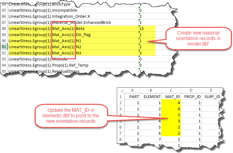
"Material(m).Mat_Axis(1).N1"
and so on.
I think that the material axis can be prescribed only in the "Egroup(e)" records, as, for instance
"LinearStress.Egroup(7).Mat_Axis(1).N1"
"LinearStress.Egroup(7).Mat_Axis(1).N2" 
 
Thus the 40 materials per group (part) have all different elastic coefficients Cij calculated (by the program) by rotating the orthotropic elastic matrix from the local cilindrical directors (determined for each element by the mean coordinate values) to the global system X,Y,Z.
 
After the c++ program run , the model table contains 11 groups of elements and 291 different materials (11 + 7*40).


At this point my program can handle only materials whose axes are aligned to the local directors of a cylindical system of coordinates, but can be easily adapted  to different situations provided that the material axis depend only by the element group and element coordinates. For instance it would be very easy to generate spherical coordinates aligned materials.  


Reply
Reply
0 Likes
Message 7 of 11

John_Holtz
Autodesk Support
Autodesk Support

Hi eulerl,


I tried my own test model. Although I was not able to duplicate your problem (error in the stress calculation) and my analysis ran to completion, I was not able to get the material orientation to work, either. So, there may be a problem in my method. I will try a different approach. Hopefully, I will have some ideas later today.


John Holtz, P.E.

Global Product Support
Autodesk, Inc.


If not provided, indicate the version of Inventor Nastran you are using.
If the issue is related to a model, attach the model! See What files to provide when the model is needed.
Reply
Reply
0 Likes
Message 8 of 11

John_Holtz
Autodesk Support
Autodesk Support

Hi,


So, are you "rotating the material properties" instead of rotating the material axis? In theory, you should be able to do either:

  1. one material and N different material axes around the cylinder
  2. OR one material axis (aligned to global X,Y,Z) and N different materials around the cylinder.

I was concentrating on method 1, but tried both. I still could not get linear stress analysis to recognize the more than one material per part or custom material orientations for the orthotropic material model.


Perhaps you can run your program on design scenario 2 of the attached archive and run the analysis. (You need to remove the .txt extension when you save it.) It should reproduce the results in design scenario 1 in which I split the model into 12 parts (12 material axes).


If it turns out that linear stress cannot handle it, some other options are:

  • Nastran InCAD may have the capability, if you have access to that software
  • MES (or nonlinear static) in Simulation Mechanical did work. I did numerous tests in order to create the PDF document that is attached.


John Holtz, P.E.

Global Product Support
Autodesk, Inc.


If not provided, indicate the version of Inventor Nastran you are using.
If the issue is related to a model, attach the model! See What files to provide when the model is needed.
Reply
Reply
0 Likes
Message 9 of 11

Anonymous
Not applicable

Hi John,


yes, i'm rotating the material properties because i didnt realize that it was possible to associate different material axis to different element properties.


Anyway , I run the design scenario 2 of the example you attached, without success: my program and the manual analysis run successful but the results are wrong: even if the elements in elements.dbf have different mat_id  (from id=3 to ID=42) SSAP0 always uses the original material number 1 !


I cannot understand why and how ssap0  associates the material 1 to the elements of group 1 because there is no record in model.dbf beginning with 

"LinearStress.Egroup(1)" or "Egroup(1)" that refer to a material ID.

The only explanation would be that group(n) uses material(n) but I refuse to accept it beause then the mat_id field in element records would be useless.


To definitevely solve the question It would be very useful to look at the code fragment in SSAP0 that assembles the contributes of brick elements or also to the similar fragment  in MKNSO. Dont you have access to the (fortran i suppose) code?


Reply
Reply
0 Likes
Message 10 of 11

John_Holtz
Autodesk Support
Autodesk Support

Hi eulerl,


I have come to the same conclusion: brick elements in linear stress analysis uses the part # of the element to get the material properties. It does not use the Mat_ID or Prop_ID column from the elements database to get the material properties. This does not mean that those columns are useless. It just means that they are used for one of the X other element types in one of the 24 other analysis types that software supports (or used to support). For example, it looks as if nonlinear analysis uses the Mat_ID column to associate the material properties of the element with a Material(I) record in the model.dbf, so that might be an option for you. (In other words, the elements database has the same format for all analyses. So if one analysis type were to require a new column, that column would appear for all of the other analysis types even though  those other types would not use any data from the column.)


As I mentioned previously, the material axes can also be oriented on a per-element basis in a nonlinear analysis. If the "analysis type" on the Element Definition is set to "Small Displacement", then you should be able to run a nonlinear static analysis with just one time step and get a solution that is comparable to a linear static analysis. The variables that need to be set are explained in the PDF attached to my previous post.


John Holtz, P.E.

Global Product Support
Autodesk, Inc.


If not provided, indicate the version of Inventor Nastran you are using.
If the issue is related to a model, attach the model! See What files to provide when the model is needed.
Reply
Reply
0 Likes
Message 11 of 11

John_Holtz
Autodesk Support
Autodesk Support

Hi eulerl,


I wanted to follow up to see if you had any thoughts or questions on this. Did you try the MES solution method?


John Holtz, P.E.

Global Product Support
Autodesk, Inc.


If not provided, indicate the version of Inventor Nastran you are using.
If the issue is related to a model, attach the model! See What files to provide when the model is needed.
Reply
Reply
0 Likes