@t.sautierr wrote:
Thanks Pawel!
So if I understand correctly, for point loads :
Can be nodal but :
need to divide the cable at each loaded node + pdelta compulsory
Can be bar loads :
no specific requirement except it exists some remaining calculation nodes along the bar, then set to "no node" in the loading table to avoid the warning.
for uniform loads : nothing to do
for loads coming from FE : i will test 🙂
Is this correct?
Yes, it is correct.
What do you mean by loads coming from FE? If you mean loads applied to panels it should work as usual. Cables can be connected to panels - but only in end nodes. If cable will be defined along the edge of some panel or inside it of course it will not connect to internal nodes of FE mesh.
t.sautier wrote:
I made the test and both model converged, but the results are quite different ...... (see data image) why ? (maybe is it the dimensions of the cable ? 10 mm section for 34 m ....... I will test the same for a more reasonable span. But let's say it is as it is, which model would you say it is the closest to reality (I would say the one with the cable into two parts ? but maybe is it because it gets more deflection so I unconsciously want to be safer).
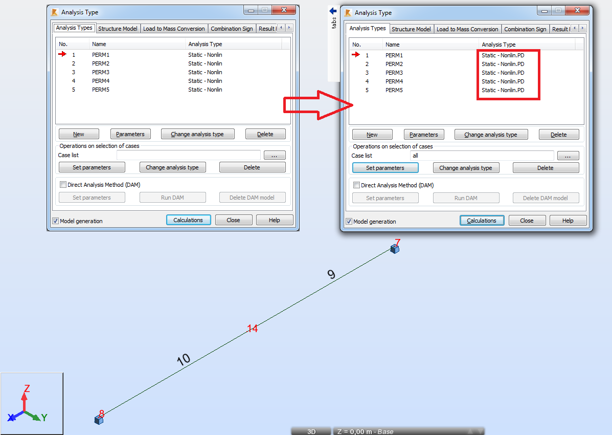
What have you tried to model in these files? The cable was defined with 0.95 relative elongation. It means that the unloaded length of cable was 95% longer that the distance of support nodes.
Such significant length results in huge sag values (about 30 meters for the span of 34 meters) and it is beyond the domain of validity of results for cables in Robot. That is why the differences between modeling cables with and without division were so significant. None of these approaches is correct in such case.
If the cable was defined this way by mistake then it is necessary to correct it. For instance when I tried 0.05 relative elongation the results for cables with and without division were similar.
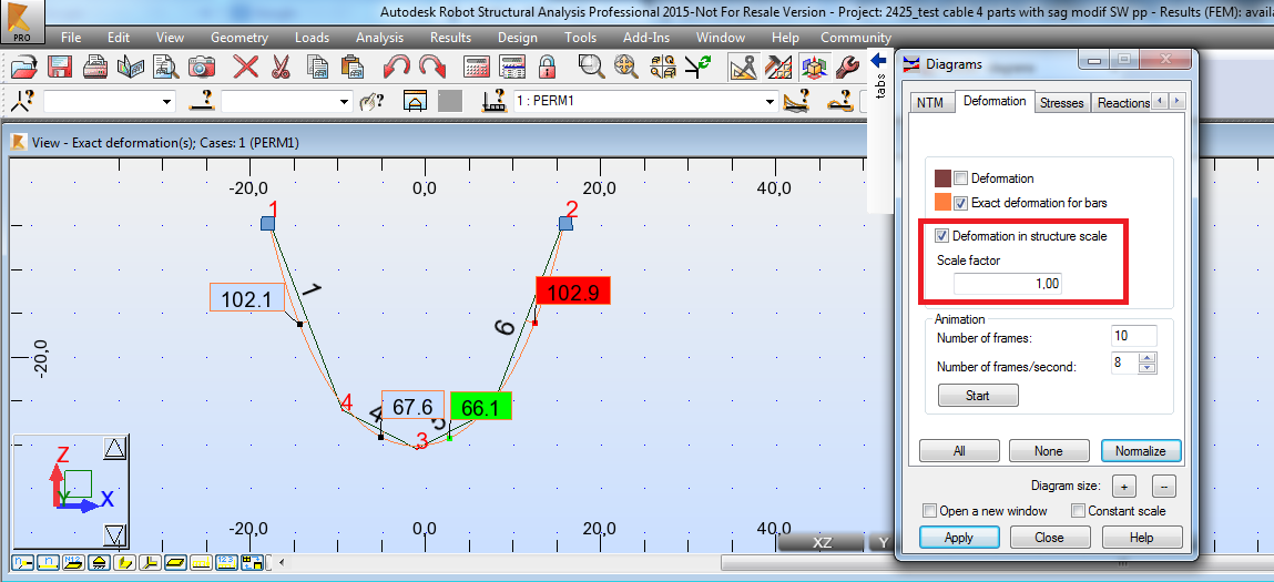
If such big cable length was used deliberately then none of these modeling methods is correct. In such case the best approach is to model it by the chain of several cables (even 4 can be enough) with zero relative elongation but predicting the deflected shape and obtaining this 95% increase of length by coordinates of nodes. This "predicted" shape does not need to be precise - Robot will find the precise deflected shape during analysis like on the screen capture below:
@t.sautierr wrote:
One last question : do we need to set the mouting case and tick the case (which always the load case with the smallest number I assume?) to be taken into account for other loads cases in the analysis table / structural model ?
Sorry - your question is not clear for me.
In case of structures containing cables the load case with the smallest number is treated as the assembling load case and it is automatically added in other load cases and combinations - it can be noticed checking the sums of forces and reactions in the table of reactions. In case of combinations the assembling load case is added only once with the factor of 1.0 - even when the assembling load case is not specified in the definition of combination. If it is directly specified with the factor different than 1.0 then this value owerwrites the default value of 1.0.
---------------------------------------------
If this post answers your question please click the "Accept as Solution" button. It will help everyone to find answer more quickly!
Regards,
 Pawel Pulak
Technical Account Specialist