Instability in rigid link nodes

Instability in rigid link nodes

Wendy_smith
Enthusiast Enthusiast
1,505 Views
22 Replies
Message 1 of 23

Instability in rigid link nodes

Wendy_smith
Enthusiast
Enthusiast

Hello,

I have placed rigid links in my model. I have W10x33 beams resting on top of W24 girder beams. The W10's are bolted to the top flange of the W24's. I placed a rigid link between the nodes for the bolt. When I run the calculation for just dead load, I have instabilities in the nodes on the W10's for the rigid link. Iam not sure what I am doing wrong. I have attached my model and a screenshot. Any help would be greatly appreciated.

Screenshot 2023-08-08 095749.png

0 Likes
1,506 Views
22 Replies
Replies (22)
Message 2 of 23

Simau
Mentor
Mentor

@Wendy_smith 

Set Bolt rigid link like this

Rigid_link RX.png

M. Agayr
Did you find this post helpful? Feel free to Like this post.
Did your question get successfully answered? Then click on the ACCEPT SOLUTION button.

EESignature

0 Likes
Message 3 of 23

Wendy_smith
Enthusiast
Enthusiast

@Simau,


Thank you for your response. Why am I setting my Bolt rigid link like that? What does that do?  What does a Welded rigid link look like? Thank you for the help.

0 Likes
Message 4 of 23

Simau
Mentor
Mentor

@Wendy_smith 


In your model, you set bolt as below


Bad Bolt config.png


Which means that your bolts don't block anything (Ux Uy an Uz are free)


In my bolt setup, to ux uy uz, i added rx to avoid instability. Bolt rx corresponds to the strong W 24x104 inertia (UY)

bolt rx.png


What does a Welded rigid link look like?

As below

Welded link.png

M. Agayr
Did you find this post helpful? Feel free to Like this post.
Did your question get successfully answered? Then click on the ACCEPT SOLUTION button.

EESignature

0 Likes
Message 5 of 23

HoshangMustafa
Advisor
Advisor

@Simau

Bolt rx corresponds to the strong W 24x104 inertia (UY)

Did you mean:

Bolt rx corresponds to the strong W 24x104 inertia (Iy)

0 Likes
Message 6 of 23

Simau
Mentor
Mentor

@HoshangMustafa 

Sorry about the typo.
Correct, its Iy

M. Agayr
Did you find this post helpful? Feel free to Like this post.
Did your question get successfully answered? Then click on the ACCEPT SOLUTION button.

EESignature

0 Likes
Message 7 of 23

HoshangMustafa
Advisor
Advisor

Hi @Simau 

Using ux uy uz, and rx blocked directions for a rigid link, how one can design the connection manually? I think these blocked directions are delivered to the connection. So how one can use these blocked directions to design the connection manually?

0 Likes
Message 8 of 23

Simau
Mentor
Mentor

@HoshangMustafa 

Below a workaround, but maybe there is a quicker solution.
Select all W10 33 members, then look at fz diagram to calculate reaction at these nodes.You may then design your bolts under these reactions.
To be conservative you can select all W 10 33 members and take design reaction as max Fz + Min Fz

w 10 33 Bolts.pngreaction.pngdesign Reaction.png

M. Agayr
Did you find this post helpful? Feel free to Like this post.
Did your question get successfully answered? Then click on the ACCEPT SOLUTION button.

EESignature

0 Likes
Message 9 of 23

Simau
Mentor
Mentor

@HoshangMustafa 

Message 8 updated (you don't need to split W10 33 members)

M. Agayr
Did you find this post helpful? Feel free to Like this post.
Did your question get successfully answered? Then click on the ACCEPT SOLUTION button.

EESignature

0 Likes
Message 10 of 23

HoshangMustafa
Advisor
Advisor

Hi @Simau 

your attached picture:

HoshangMustafa_0-1693232066531.png


there seems to exist 4 bolts, two on each side, correct?

In the model, there exists only one rigid link at this place, isn't it?

How one can use (one) rigid link results to design these (4) bolts?

0 Likes
Message 11 of 23

Simau
Mentor
Mentor

@HoshangMustafa 

Yes there are 4 bolts (but its only an example). A bolt is designed with Reaction/4
You may use the classic scheme:

Echantignole.png

M. Agayr
Did you find this post helpful? Feel free to Like this post.
Did your question get successfully answered? Then click on the ACCEPT SOLUTION button.

EESignature

0 Likes
Message 12 of 23

HoshangMustafa
Advisor
Advisor

Hi @Simau 

you wrote:

A bolt is designed with Reaction/4

This is for gravity loads. For lateral loading (i.e., wind load) how rigid link can be applied if there is eccentricity?

0 Likes
Message 13 of 23

Simau
Mentor
Mentor

@HoshangMustafa 

Please complete your model with loads you need and create combiations. If you apply wind loads to claddings, efforts will be mostly parallel to local axis Z of the purlins.

Look at "reactions" in local axis  x y z , you will find that the efforts in the x and y directions are negligible.


M. Agayr
Did you find this post helpful? Feel free to Like this post.
Did your question get successfully answered? Then click on the ACCEPT SOLUTION button.

EESignature

0 Likes
Message 14 of 23

HoshangMustafa
Advisor
Advisor

Hi @Simau 

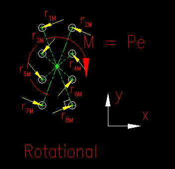
ignore lateral load, assume gravity load as follow:


Can rigid link simulate this condition?

0 Likes
Message 15 of 23

Simau
Mentor
Mentor

@HoshangMustafa 

Yes, just add Rz as blocked direction in bolt parameters


bolts.png


M. Agayr
Did you find this post helpful? Feel free to Like this post.
Did your question get successfully answered? Then click on the ACCEPT SOLUTION button.

EESignature

0 Likes
Message 16 of 23

HoshangMustafa
Advisor
Advisor

Hi @Simau 

My concern was about the share of each bolt from the load, i.e., rigid link simulating for this case (a group of bolts, each bolt receiving a share of load based on its distance from the load).

0 Likes
Message 17 of 23

Simau
Mentor
Mentor

@HoshangMustafa 

It's not possible.
The rigid link will give you the the whole torsional moment , but not the sharing of this moment between the bolts. You have to calculate the distribution manually.

You may  try a small model simulating this connection (see model attached)

M. Agayr
Did you find this post helpful? Feel free to Like this post.
Did your question get successfully answered? Then click on the ACCEPT SOLUTION button.

EESignature

0 Likes
Message 18 of 23

HoshangMustafa
Advisor
Advisor

Hi @Simau 

Can you upload the model with earlier version (2018)?

0 Likes
Message 19 of 23

Simau
Mentor
Mentor

@HoshangMustafa 

Very sorry, but old versions are no longer installed here.

M. Agayr
Did you find this post helpful? Feel free to Like this post.
Did your question get successfully answered? Then click on the ACCEPT SOLUTION button.

EESignature

0 Likes
Message 20 of 23

Simau
Mentor
Mentor

@HoshangMustafa 

here is what I modeled.
A steel plate on 6 supports subjected to a torsion moment of 100 kNm


1.png2.png


M. Agayr
Did you find this post helpful? Feel free to Like this post.
Did your question get successfully answered? Then click on the ACCEPT SOLUTION button.

EESignature

0 Likes