Community
- Forums Home
- >
- Robot Structural Analysis Products Community
- >
- Robot Structural Analysis Forum
- >
- Re: 3D model result
Announcements
Due to scheduled maintenance, the Autodesk Community will be inaccessible from 10:00PM PDT on Oct 16th for approximately 1 hour. We appreciate your patience during this time.
Robot Structural Analysis Forum
Welcome to Autodesk’s Robot Structural Analysis Forums. Share your knowledge, ask questions, and explore popular Robot Structural Analysis topics.
Turn on suggestions
Auto-suggest helps you quickly narrow down your search results by suggesting possible matches as you type.
Reply
Topic Options
- Subscribe to RSS Feed
- Mark Topic as New
- Mark Topic as Read
- Float this Topic for Current User
- Bookmark
- Subscribe
- Printer Friendly Page
Message 1 of 13
10-18-2023
04:55 AM
- Mark as New
- Bookmark
- Subscribe
- Mute
- Subscribe to RSS Feed
- Permalink
- Report
10-18-2023
04:55 AM
Hello,
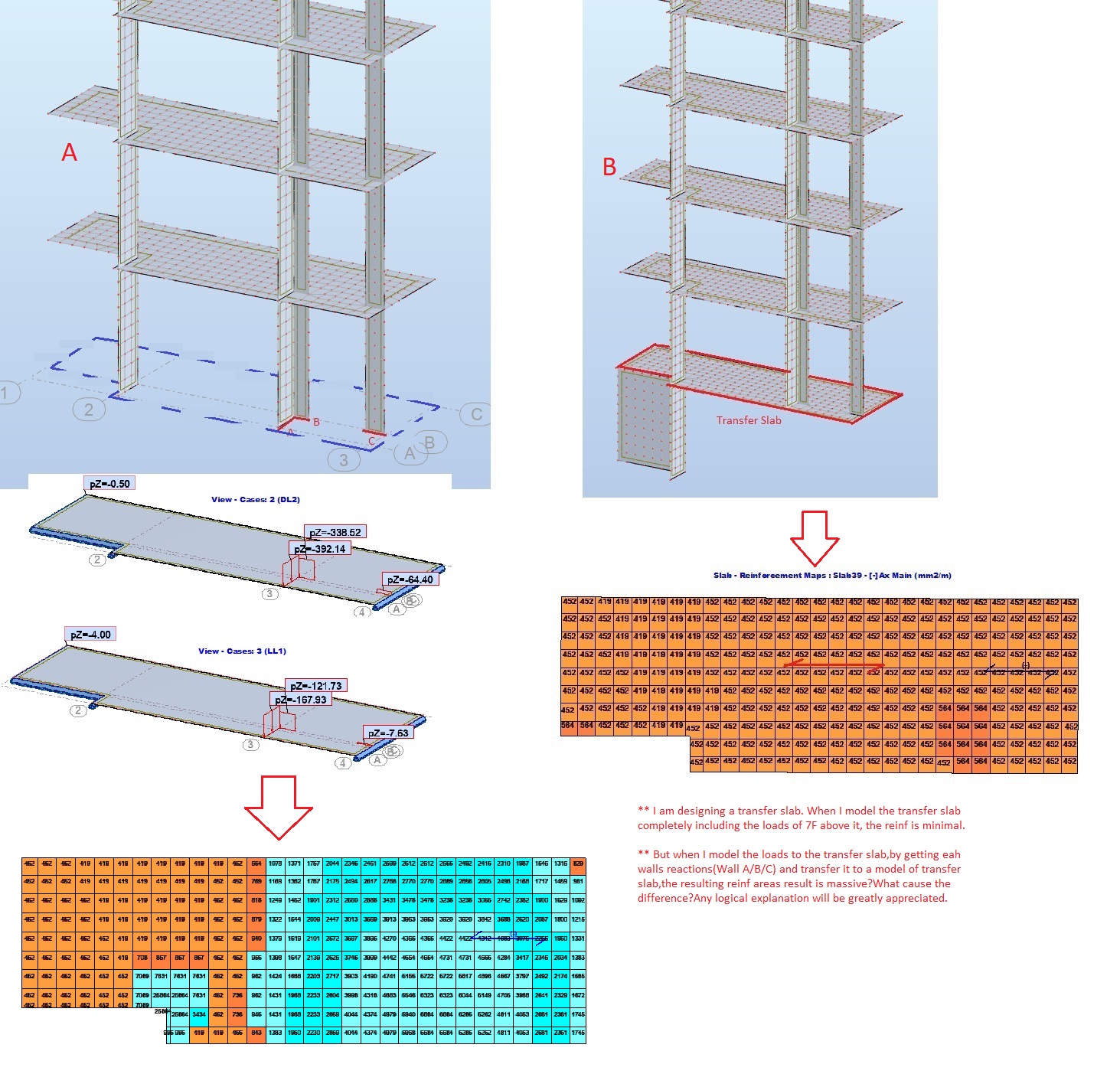
** I am designing a transfer slab. When I model the transfer slab completely including the loads of 7F above it, the reinf is minimal.
** But when I model the loads to the transfer slab,by getting each walls reactions(Wall A/B/C) and transfer it to a model of transfer slab,the resulting reinf areas result is massive?What cause the difference?Any logical explanation will be greatly appreciated. Pls. see attached
Solved! Go to Solution.
Solved by Krzysztof_Wasik. Go to Solution.
12 REPLIES 12
Message 2 of 13
10-18-2023
05:49 AM
- Mark as New
- Bookmark
- Subscribe
- Mute
- Subscribe to RSS Feed
- Permalink
- Report
10-18-2023
05:49 AM
Hi @saclovitzky
In model B the following panels transfer tension.

So in my opinion load from those panels does not correspond to exuivalent load defined in model B (you have supposed compression transferred to the slab)

Krzysztof Wasik
Message 3 of 13
10-18-2023
05:56 AM
- Mark as New
- Bookmark
- Subscribe
- Mute
- Subscribe to RSS Feed
- Permalink
- Report
Message 4 of 13
10-18-2023
06:17 AM
- Mark as New
- Bookmark
- Subscribe
- Mute
- Subscribe to RSS Feed
- Permalink
- Report
10-18-2023
06:17 AM
Hi @saclovitzky
Load transferred by core wall (replaced by loads) is still much smaller than applied equivalent load.
In my opinion you have not considered slab flexure deformation while calculating equivalent forces.


All slabs deforms more or less by the same value so there is no reason for transferring significant forces by core

wall.
Krzysztof Wasik
Message 5 of 13
10-18-2023
06:25 AM
- Mark as New
- Bookmark
- Subscribe
- Mute
- Subscribe to RSS Feed
- Permalink
- Report
10-18-2023
06:25 AM
@Krzysztof_Wasik Basically in essence, the 3D model in "B" which includes the transfer slab is more practical model in designing the transfer slab?
Likewise, in "A" it is really very conservative?But one more thing,when I put pinned supports on the 3 walls,it gives walls reactions that is actually huge!but as you have shown,the actual load on the walls(where you cut a section) is very low(3D model with transfer slab)! Any reason for this?
Message 6 of 13
10-18-2023
07:11 AM
- Mark as New
- Bookmark
- Subscribe
- Mute
- Subscribe to RSS Feed
- Permalink
- Report
10-18-2023
07:11 AM
**For comparison purposes, I check the "reduced result" of panel 5 with transfer slab model,then with same model,I delete the transfer slab and put pinned support for the 3 walls. And the difference of the loads are pretty massive, did I missed something here? I expect that the loads being transmitted to the transfer slab should be the same(considering that I used the same model)?
Pls. see attached files.
Message 7 of 13
10-18-2023
07:20 AM
- Mark as New
- Bookmark
- Subscribe
- Mute
- Subscribe to RSS Feed
- Permalink
- Report
10-18-2023
07:20 AM
Hi @saclovitzky Increase stiffness (thickness of the bottom plate) and you will obtain similar effect. You assume that bottom plate works as rigid support for core wall. It is not true due to slab deflection.
Krzysztof Wasik
Message 8 of 13
10-18-2023
07:22 AM
- Mark as New
- Bookmark
- Subscribe
- Mute
- Subscribe to RSS Feed
- Permalink
- Report
Message 9 of 13
10-18-2023
07:32 AM
- Mark as New
- Bookmark
- Subscribe
- Mute
- Subscribe to RSS Feed
- Permalink
- Report
10-18-2023
07:32 AM
@Krzysztof_Wasik In you opnion, the reduced result(panel 5) taken from the 3D model with the transfer slab,is the "correct" loadings for Transfer Slab(pls. see attached)
Message 10 of 13
10-18-2023
07:44 AM
- Mark as New
- Bookmark
- Subscribe
- Mute
- Subscribe to RSS Feed
- Permalink
- Report
10-18-2023
07:44 AM
Hi @saclovitzky
If you increase bottom slab thickness you will reduce possibility of its deformation . In that case loads transferred by core wall should be bigger. Bigger for bigger bottom slab thickness. For such model version (members stiffness distribution) there is no reson for considering forces presented by program as incorrect.
- Hi
Krzysztof Wasik
Message 11 of 13
10-18-2023
07:56 AM
- Mark as New
- Bookmark
- Subscribe
- Mute
- Subscribe to RSS Feed
- Permalink
- Report
10-18-2023
07:56 AM
@Krzysztof_Wasik I'm really interested to know the actual loads that needs to be transferred to the transfer slab when I want to model the transfer alone;
My final questions are:
1. Is it correct to model a 3D model with walls A, B and C with pinned support?My assumption is that,when I get the reactions(walls A/B/C) that would be an appropriate loadings for the transfer slab(Is this correct?). there's no need for me to include the trnasfer slab in this model because I am "only" interested to the loads that will be transferred to the "transfer slab".
2. Also, in creating a 3D model with a transfer slab,is it reliable to get the "reduced result" of walls A/B/C(Axial loads) and used it as the loads for the "transfer slab"?
Again, thank you very much for your time.
Message 12 of 13
10-18-2023
02:17 PM
- Mark as New
- Bookmark
- Subscribe
- Mute
- Subscribe to RSS Feed
- Permalink
- Report
10-18-2023
02:17 PM
Hi @saclovitzky
ad1
It is conservative approach. You assume the transfer slab does not deform.
Using conservative approach you divide system in two parts.
Defining model with all walls pinned and using reactions as loads for transfer slab isolated from the model is acceptable (conservative) solution.
ad2.
In your 3D system defined together with transfer slab, forces transferred (especially by walls A and B ) depends on transfer slab stifness. Your 3D model is hyperstatic system.
When you define the same thickness for all slabs, transfer slab does not act as support for whole system above it. In my opinion forces in walls A and B (also obtained using reduced results for panels) are underestimated because transfer slab in the model is not rigid enough. I would not use them (reduced forces) for load definition when transfer slab is isolated from the system.
Krzysztof Wasik
Message 13 of 13
10-19-2023
04:01 AM
- Mark as New
- Bookmark
- Subscribe
- Mute
- Subscribe to RSS Feed
- Permalink
- Report
10-19-2023
04:01 AM
@Krzysztof_Wasik . I agree with you Ad1 is a very conservative approach!Which is on the safe side.
While Ad2,is what actually in real life situation(I guess), but low values result (reduced result for panels),is due to the fact that all slabs above the transfer slab have the same stiffness/deflection. Although,when we design the transfer slab and do the manual load take down, we assumed that all loads are coming down(compression) to transfer slab(disregarding the stiffness of the upper slab etc.).
Any way thanks for your explanation on this 🙂
Reply
Topic Options
- Subscribe to RSS Feed
- Mark Topic as New
- Mark Topic as Read
- Float this Topic for Current User
- Bookmark
- Subscribe
- Printer Friendly Page
Forums Links
Can't find what you're looking for? Ask the community or share your knowledge.
Post to forums
