Community
- Forums Home
- >
- Revit Products Community
- >
- Revit Architecture Forum
- >
- Phasing Graphics and Detail Level
Revit Architecture Forum
Welcome to Autodesk’s Revit Architecture Forums. Share your knowledge, ask questions, and explore popular Revit Architecture topics.
Turn on suggestions
Auto-suggest helps you quickly narrow down your search results by suggesting possible matches as you type.
Reply
Topic Options
- Subscribe to RSS Feed
- Mark Topic as New
- Mark Topic as Read
- Float this Topic for Current User
- Bookmark
- Subscribe
- Printer Friendly Page
Message 1 of 30
Anonymous
4759 Views, 29 Replies
12-18-2015
11:02 AM
- Mark as New
- Bookmark
- Subscribe
- Mute
- Subscribe to RSS Feed
- Permalink
- Report
12-18-2015
11:02 AM
Phasing Graphics and Detail Level
Working in Revit LT 2014.
We want to use Revit's phasing functionality to differentiate between existing and proposed building elements. However, we also want to show building elements at a fine detail level (ie wall layers). I have read that one should be able to achieve this by going to the graphic overrides tab on the phasing menu and selecting "no material" (click inside the box on the material column, then click the …, then click the 'no material' button on the bottom left). It isn't working, however.
I double checked that my view template is actually set to the fine detail level.
Is there another interrelated setting somewhere I might need to change? Or maybe I can't do this with Revit LT?
29 REPLIES 29
Message 2 of 30
12-18-2015
11:35 AM
- Mark as New
- Bookmark
- Subscribe
- Mute
- Subscribe to RSS Feed
- Permalink
- Report
12-18-2015
11:35 AM
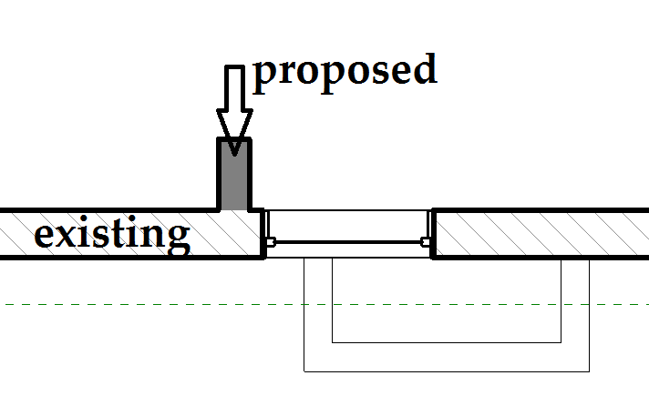
I assume you are trying to do somethign like this:

You can't do this using phasing. When a graphic override is applied based on the state (existing, new, demo, temporary) of an element ALL of the materials of the element are replaced with the material listed in the phasing dialog. Switching out to "no material" really applies no material quality at all. What you would be looking for in Revit terms would be "By Category" but this is not an option in the dialog.
I achieved the image above by selecting the elements manually and applying an element level override of halftone. I did this in Revit LT. Is is only slightly easier in 'Full' Revit because I can build a selection filter to quickly select the existing elements and apply a specific graphic override, but it is still a manulal process.
Message 3 of 30
12-18-2015
11:59 AM
- Mark as New
- Bookmark
- Subscribe
- Mute
- Subscribe to RSS Feed
- Permalink
- Report
12-18-2015
11:59 AM
I'm surprised that you say it's not possible because this article from Autodesk says that it is.
Message 4 of 30
12-18-2015
12:02 PM
- Mark as New
- Bookmark
- Subscribe
- Mute
- Subscribe to RSS Feed
- Permalink
- Report
12-18-2015
12:02 PM
Perhaps in an older version (but I don't think so). I tried doing exactly this but it does not work in 2016. Just based on the way I understand this control to work I don't think it ever worked. I will look into who posted the solution and see.
Message 5 of 30
12-18-2015
12:28 PM
- Mark as New
- Bookmark
- Subscribe
- Mute
- Subscribe to RSS Feed
- Permalink
- Report
12-18-2015
12:28 PM
Ok messing with a bit more I found a way you can get a bit closer using the solution you linked to, but it is missing a couple of steps. You can do everythign the solution says, but in addition you need to click on the cut pattern override box and click "visible". This will turn on the layers in the existing wall.


But notice this might not be what you want either. The layers of the wall are on, but if the layers have any fill patterns they will NOT be halftone. Either way the solution needs to be updated to have the additional steps. As written it does not work.
Message 6 of 30
12-18-2015
12:54 PM
- Mark as New
- Bookmark
- Subscribe
- Mute
- Subscribe to RSS Feed
- Permalink
- Report
12-18-2015
12:54 PM
Great, so it sounds like this should work.
I have the box for cut pattern visibility that you indicate checked, so it should be on. Still not working. Did you ever find the person who posted that article? That person might know more about how it works.
Message 8 of 30
12-19-2015
02:11 AM
- Mark as New
- Bookmark
- Subscribe
- Mute
- Subscribe to RSS Feed
- Permalink
- Report
12-19-2015
02:11 AM
loboarch -
You should note that with your settings, saying that you existing phase gets halftoned is not correct. The projection and cut lines are overridden to be gray, but the halftone option is not checked. Instead, clear the overrides for the projection and cut lines, and check the halftone option. You may find that your cut patterns aren't black anymore.
Message 9 of 30
12-21-2015
09:19 AM
- Mark as New
- Bookmark
- Subscribe
- Mute
- Subscribe to RSS Feed
- Permalink
- Report
12-21-2015
09:19 AM
chrisplyler-
Do you have any ideas about why this process wouldn't be working for me? I'm trying to display a fill pattern to differentiate phases while still displaying the fine detail level.
As noted previously in the thread, I have selected "no material" in the graphics override tab of the phasing menu, and the "visible" option that loboarch described is checked. The view template is set to fine detail, but it is still displaying as course.
Message 10 of 30
12-21-2015
11:58 AM
- Mark as New
- Bookmark
- Subscribe
- Mute
- Subscribe to RSS Feed
- Permalink
- Report
12-21-2015
11:58 AM
As previously explained, the existing phase sets one material for every layer in the wall, even if you choose "no material" they are all set the same. So effectively there are no separate material layers to display. That's why the existing wall looks course even with your view set to fine detail level. I don't know of any way to do it differently, except to avoid setting anything to the existing phase and instead grayscale them via by-element overrides.
Message 11 of 30
12-21-2015
12:55 PM
- Mark as New
- Bookmark
- Subscribe
- Mute
- Subscribe to RSS Feed
- Permalink
- Report
12-21-2015
12:55 PM
Chrisplyler, you are correct: loboarch did explain the same thing you explained. I wonder if you saw my response? I pointed out that this article from autodesk indicates that it IS possible to do what I'm trying to do. Subsequently loboarch seems to have tried it and had success. In the images he posted, it shows that he was able to have graphic overrides by phase and, at the same time, display the fine detail level.
It might be helpful for everyone and less frustrating for you guys if you could find the person who wrote that article to help troubleshoot this.
Message 12 of 30
12-21-2015
01:40 PM
- Mark as New
- Bookmark
- Subscribe
- Mute
- Subscribe to RSS Feed
- Permalink
- Report
12-21-2015
01:40 PM
Yes I apologize. I'm afraid I'm not any smarter than Loboarch on this matter. But I WAS trying to help you regardless.
But I am not frustrated even a tiny bit. I don't happen to have a problem displaying phase=existing elements as I desire. I am not an Autodesk employee. I am merely a Revit user like you who happens to like helping when I can. Perhaps YOU should hunt down the person who wrote the article, hmmm?
Message 13 of 30
12-21-2015
01:46 PM
- Mark as New
- Bookmark
- Subscribe
- Mute
- Subscribe to RSS Feed
- Permalink
- Report
12-21-2015
01:46 PM
I would love to find the person who wrote that article! Posting on this forum is the only way I can think of to do that.
Chrisplyler, I'm sorry for mistakenly thinking you worked for Autodesk. Thank you for trying to help!
Message 14 of 30
12-21-2015
02:27 PM
- Mark as New
- Bookmark
- Subscribe
- Mute
- Subscribe to RSS Feed
- Permalink
- Report
12-21-2015
02:27 PM
It is possible using Phase filter setting. Look at the screenshot and the attached Revit file (2013).

Toan Nguyen
Did you find this post helpful? Feel free to Like this post.
Did your question get successfully answered? Then click on the ACCEPT SOLUTION button.
Message 15 of 30
12-21-2015
02:33 PM
- Mark as New
- Bookmark
- Subscribe
- Mute
- Subscribe to RSS Feed
- Permalink
- Report
12-21-2015
02:33 PM
Thank you, ToanDN. I understand that you can use the halftone setting to differentiate between phases and display the fine detail level.
To reiterate, I am hoping to differentiate between phases using a fill pattern while also displaying the fine detail level.
Message 16 of 30
12-21-2015
02:48 PM
- Mark as New
- Bookmark
- Subscribe
- Mute
- Subscribe to RSS Feed
- Permalink
- Report
12-21-2015
02:48 PM
Do you want a combination of Coarse and Fine scale graphics? I don't think the article you referred to saying you could do that.
Try combine Phase filter setting and View filter then.

Toan Nguyen
Did you find this post helpful? Feel free to Like this post.
Did your question get successfully answered? Then click on the ACCEPT SOLUTION button.
Message 17 of 30
12-21-2015
03:09 PM
- Mark as New
- Bookmark
- Subscribe
- Mute
- Subscribe to RSS Feed
- Permalink
- Report
12-21-2015
03:09 PM
I'm not sure I understand what you mean when you ask, "Do you want a combination of Coarse and Fine scale graphics?" What I am trying to do is exactly what that article discussed: changing the detail display of overriden phases.
To clarify, the attached screen shot shows our office standards for differentiating between existing and proposed walls. Existing walls have a diagonal line fill pattern, and proposed walls have a solid grey fill pattern. We would like to be able to use phase graphics to display these fill patterns AND show the layers within the walls. I hear that the steps outlined in this article work for other people, but they are not working for me.
Message 18 of 30
12-21-2015
03:31 PM
- Mark as New
- Bookmark
- Subscribe
- Mute
- Subscribe to RSS Feed
- Permalink
- Report
12-21-2015
03:31 PM
What your screenshot shows is Coarse detail, and you also want to show the wall component layers which is Fine detail, so that you happened to answers my question about combination of the two.

Toan Nguyen
Did you find this post helpful? Feel free to Like this post.
Did your question get successfully answered? Then click on the ACCEPT SOLUTION button.
Message 19 of 30
12-21-2015
06:31 PM
- Mark as New
- Bookmark
- Subscribe
- Mute
- Subscribe to RSS Feed
- Permalink
- Report
12-21-2015
06:31 PM
Aha! Loboarch is indeed smarter than me!!! So...
1. "No Material" applied in the phase graphic settings, to keep the wall layers from disappearing, and...
2. A view filter applied to give it the cut pattern.
The only issue is that it won't be completely automatic, because the filter cannot trigger off of the Phase parameter; you still have to use the Comment field to trigger the filter. But that's a pretty minor gripe I think. You could have a view that shows only the existing stuff, so that you can easily select all the existing walls and set their Comments parameter all at once.
kittyj - I'm curious how your graphical standards allow for the identification of new wall layer materials...since you show every layer in the same gray shading instead of using various hatch patterns. Do you tag wall types and use some sort of schedule or legend to spell out the layer materials in each type?
Message 20 of 30
12-22-2015
05:11 AM
- Mark as New
- Bookmark
- Subscribe
- Mute
- Subscribe to RSS Feed
- Permalink
- Report
12-22-2015
05:11 AM
chrisplyler wrote:
Aha! Loboarch is indeed smarter than me!!!
Of course I am! ![]()
chrisplyler wrote:
2. A view filter applied to give it the cut pattern.
In this case that will not work because the OP said they are using Revit LT. There are not view filters in Revit LT. Doen't mean it can't be done just means it is a heck of a lot more work because the visibility/graphics of elements need to be manually altered.
This is one of those cases where I would start to think about the office graphic standard and begin to weigh how important the look of the view printed or on screen actually is vs. how much extra work you need to do to get there. Revit offers the phasing tools to handle these graphic changes "automatically" so you can get them to be visibly different without much difficulty and almost no chance for errors or you can manually change the graphics of elements to match the standard (or atleast get close) but have potential for errors and spend a lot of time doing it. Or if it is that important, then perhaps Full Revit is a better software choice because you can use view filters to make it "kind of" automatic. (Of course the 3rd one is the one I advocate for as an employee of Autodesk ![]() )
)
As for the author of the original article mentioned, the system that was used to create the article gives me no way to see the original author. it was written quite some time ago as we have not used that creation tool for a long time. The article needs to be updated as it is wrong now and actually I doubt if the steps in the article really ever did what is being asked.
Reply
Topic Options
- Subscribe to RSS Feed
- Mark Topic as New
- Mark Topic as Read
- Float this Topic for Current User
- Bookmark
- Subscribe
- Printer Friendly Page
Forums Links
Can't find what you're looking for? Ask the community or share your knowledge.
Post to forums

