CreateViaOffset(CurveLoop original,IList<double> offsetDists,XYZ normal

CreateViaOffset(CurveLoop original,IList<double> offsetDists,XYZ normal

stephen_harrison
Advocate Advocate
8,192 Views
27 Replies
Message 1 of 28

CreateViaOffset(CurveLoop original,IList<double> offsetDists,XYZ normal

stephen_harrison
Advocate
Advocate

I hope someone can help.

I have raised a previous post regarding Generating Views from rooms but feel that has probably run its course.

The problem I now face is how to follow the outer face of the wall were the wall changes thickness over its length and when room separators are utilised.

When the walls step back like image 1 there is an error “Curve loop couldn't be properly trimmed”.

Image1.png

Regarding room separators, the problems occur when the separator is as image 2, Error “Curve loop couldn't be properly trimmed”.
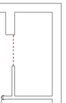
Image2.png

Situations like Images 3 there has been no errors so far!
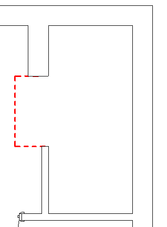
Image3.png

I am working in c# with Revit 2020 and utilising the following to create the offset:


CreateViaOffset(CurveLoop original,IList<double> offsetDists,XYZ normal)


IList<double> is the thickness of the surrounding walls and a standard set offset for the room separator.


Is this a problem with the API or is there a solution to my problem that I am missing.

Any assistance is much appreciated.

0 Likes
Accepted solutions (1)
8,193 Views
27 Replies
Replies (27)
Message 21 of 28

stephen_harrison
Advocate
Advocate

Hi Jeremy, finally manged to find a few minutes today to look at converted JTLoop to CurveLoop as follows:

CurveLoop newloop = new CurveLoop();
                List<XYZ> points = new List<XYZ>();
                foreach (JtLoop cloops in loops)
                {
                    foreach (Point2dInt p in cloops)
                    {
                        XYZ start = new XYZ(p.X , p.Y , 0);
                        points.Add(start);
                    }
                    int repearFirst = points.Count - 1;
                    for (int ip = 0; ip < points.Count; ip++)
                    {
                        if (ip != points.Count - 1)
                        {
                            Line l = Line.CreateBound(points[ip]/ (int)System.Math.Round(25.4 * 12), points[ip + 1]/ (int)System.Math.Round(25.4 * 12));
                            newloop.Append(l);
                        }
                        else
                        {
                            Line l = Line.CreateBound(points[ip] / (int)System.Math.Round(25.4 * 12), points[ip - repearFirst] / (int)System.Math.Round(25.4 * 12));
                            newloop.Append(l);
                        }
                    }
                }

I am sure there will be a far more elegant way of achieving this but it does appear to work.

I thought you would like to know however there does appear to be a few issues with the Element Outline solution:

1) When the room is not a simple contained element and the rooms walls extend beyond the confines of the room the following results:

MultiRoom Error.pngMultiRoom Error2.png

2) the instant doors, windows etc are introduced the following results:

Outline Door Error.pngOutline Window Error.png


Regards

Stephen

0 Likes
Message 22 of 28

jeremytammik
Autodesk
Autodesk

Congratulations on the good progress and new interesting results.


Yes, I guess that could be elegantified a bit...


Example 1 is very nice, isn't it? Pretty obvious, though. The algorithm absolutely does its job. Fixing that would require some additional intelligence, e.g., an algorithm to chop off bits of bounding elements that extend way too far beyond the interior room boundary.


Example 2 is a bit weird. I cannot explain that. Can you? Please implement code to highlight the individual footprint of each bounding element, e.g., using model lines, so that you can see where the thickened wall segment originates.


Jeremy Tammik
Developer Technical Services
Autodesk Developer Network, ADN Open
The Building Coder

0 Likes
Message 23 of 28

stephen_harrison
Advocate
Advocate

Jeremy

Further to the example 2 issues find below images of the two previously posted examples but with offset Element Outline highlighted in Red.

Outline Door Error RedLine.pngOutline Window Error RedLine.png

What appears to be happening I believe is as the loop moves around the perimeter of the room at the first contact with a door or window it cause the loop to come into the wall as though it is interpreting this as the end of a wall?  Although if that was the case why are the points at which the redline turns into the wall for the door and window at different points? Im baffled, but that's not very difficult some times!

It would be nice as a solution if it could follow the outline of the door/window very much like the desk example which is what I expected to happen!

https://thebuildingcoder.typepad.com/blog/2020/01/extrusion-analyser-and-2d-boolean-element-outline.... 


Regards

Stephen

0 Likes
Message 24 of 28

stephen_harrison
Advocate
Advocate

Jeremy

Further to my post above highlighting in red the outline produced from the Room Outer Outline and my further endeavours to identify why we are getting these results, regrettably with no success. 

I decided to run the same test utilising Element Outline Solid and Element Outline 2D Boolean. Interestingly the problem does not appear to occur when using Element Outline Solid.


Element Outline Solid

Element Outline Solid.png 

Element Outline 2D Boolean

E;ement Outline 2D Booleans.png

Regrettably despite my best endeavours I am unable to ascertain why and a solution, it would appear this level of codding is currently a step to far for me!

Thank you for all your assistance, it is something I will have to return to once I have more experience!

Regards

Stephen

0 Likes
Message 25 of 28

jeremytammik
Autodesk
Autodesk

Thank you for the interesting and very promising results.


Obviously, everything you need to solve the task is now available in one for or another.


All that is missing is to put it together.


The element solids are united into one that is processed with the Revit API extrusion analyser class to generate the outline Revit curve elements. These are used to produce model curves in the document. 


You would need to grab those outline curve elements and feed them into the 2D Boolean processing to generate 2D areas from them and unite them with the room outer outline solid. No big deal, really. Much easier than what I already implemented for you, all in all.


If you give me some time, I will gladly do so for you.


Unfortunately, I do not believe anybody has ever been able to do that yet in the history of mankind... give time, I mean.


We all have to make do with what we are given.


Jeremy Tammik
Developer Technical Services
Autodesk Developer Network, ADN Open
The Building Coder

0 Likes
Message 26 of 28

stephen_harrison
Advocate
Advocate

Jeremy

Thank you again for your response. I will endeavour to work on the solution based on your latest comments, however considering how much I have struggled with this you have as much time as you need and will no doubt still beat me to the solution.

As you say "We all have to make do with what we are given."

Regards

Stephen

0 Likes
Message 27 of 28

jeremytammik
Autodesk
Autodesk

As long as your walls, doors and windows are all perpendicular, you could actually just create the 2D Boolean union for the outer room outline from the room interior footprint plus all the wall and family instance bounding boxes. That would certainly be the simplest solution for the two case you describe last. 


Jeremy Tammik
Developer Technical Services
Autodesk Developer Network, ADN Open
The Building Coder

0 Likes
Message 28 of 28

Anonymous
Not applicable

Hi Jeremy,

I've implemented Your code from GitHub. Although there's a branch if(Elm ==null){ lstwallthickness.Add(-0.1); } in my code I'm still getting the same error again. BoundarySegment s in looping has ElementId and LinkedElementId  set to -1.

The Project is attached.

Any ideas what can it be?

0 Likes