Automation of repeatable parts

Automation of repeatable parts

SRayne44
Explorer Explorer
728 Views
4 Replies
Message 1 of 5

Automation of repeatable parts

SRayne44
Explorer
Explorer

Good Morning, 

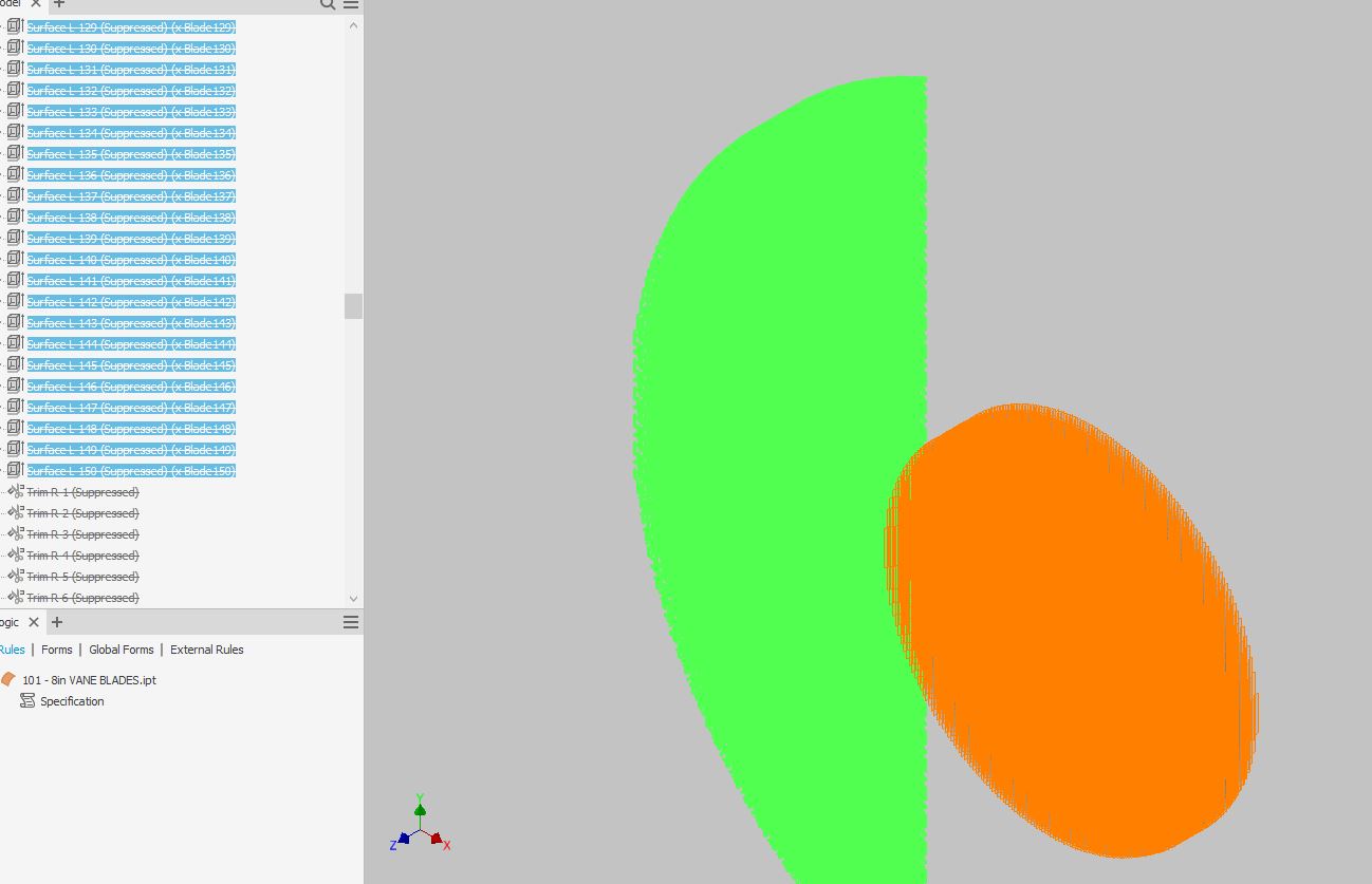
I have a problem I've been trying to solve for ages now.  In our company we build products called Vane Packs.  The packs are a collection of "Vane Blades" cut to length (straight end cut) to fit in a specific inner diameter. 


Every blade is the same geometry, the only thing that changes is the length and distance (offset) from center line.  I have tried to automate this many times using master sketches with each profile for each blade and then extruding each as a surface, but the bigger it gets the slower it updates and the more snippet code I need to write to suppress a surface if it falls outside of the Inner Diameter. 


Is there a way that I can just have 1 master Blade part, that can be added into an assembly with the length and offset being the only things that really change?


Any help/input would be awesome, as I'm at my wits end trying to figure this out. 


Attached is an image of the product in question. 

0 Likes
729 Views
4 Replies
Replies (4)
Message 2 of 5

WCrihfield
Mentor
Mentor

How do you currently create these parts?  From scratch, partially manually & partially by code ; or entirely by code.  Are you creating each as a 'New' document from a Template, or are you copying an existing model document, then modifying?  Is each 'Vane' a separate Part, or is the model in the image a multi-body part?


My first thoughts would be to have a master part file (as an actual Template), then through use all named user parameters, a Form, and iLogic rules, to create a configuration Template part.  Then just click New, fill out Form, rules then run, and boom new model to specs.  But it may take a lot of work to get to that point.

Wesley Crihfield

EESignature

(Not an Autodesk Employee)

Message 3 of 5

SRayne44
Explorer
Explorer

I currently have a Master sketch file, with a Shell Diameter, a sketch of the blade profile which is patterned off center by the spacing required.  This pattern exceeds (on purpose) the Shell diameter up to a number of blades I consider a maximum (150 left, 150 right), inside that Master sketch in Ilogic I have a rule that calculates each blades length as it gets closer to the edge of the Shell Diameter, and any blades that fall outside that are left with a uncalculated dimension. 


From there I derived an .ipt file from the Master and painfully extruded a surface for each of the blade lengths (150 left, 150 right), and then had to write a rule that if any blades fell outside the shell diameter that the surface extrusion was suppressed.  This process however takes probably 15-25 mins to update anytime the shell diameter is changed.  Which just doesn't help workflow at all and I could draw it in 2D cad in 1/4 of that time. 


Attached is a sample of the master file and a sample image of the derived .ipt file. 

0 Likes
Message 4 of 5

WCrihfield
Mentor
Mentor

Wow.  That looks a lot more complicated that I had imagined.  Without having any of your product knowledge about this or having all the specifics of your design intent, this kind of seams like it might be a bigger task that I would want to take on remotely.  You may have to break this task down into smaller 'bite size' chunks and tackle it one step at a time, if you want help fully automating it.  Just my opinion though.  There are lots of others here on the forums that may be able to tackle a larger task like this though.

Wesley Crihfield

EESignature

(Not an Autodesk Employee)

0 Likes
Message 5 of 5

Michael.Navara
Advisor
Advisor

This is very nice task😀

This automation task is my core business and I can help you with it. If you are interested, you can contact me in private message.

Here is few information and samples

https://www.cadstudio.cz/en/csconfigurator.asp


0 Likes