Min and Max Markers Change with Section View

Min and Max Markers Change with Section View

jonathan.p.kelly
Enthusiast Enthusiast
1,717 Views
3 Replies
Message 1 of 4

Min and Max Markers Change with Section View

jonathan.p.kelly
Enthusiast
Enthusiast

Hello all,


I am using Inventor Nastran 2020.


I am new to working with thermal analyses in Nastran and am working with a test model to help me understand what is going on and how the program responds.  I performed a Nonlinear Transient Heat Transfer on a block with the following loads:


Initial Condition:  50 F

Heat Generation:  Time dependent

Convection:  Time dependent


I believe that the program is running correctly, though I know that the input values for the heat generation load are unreasonable.


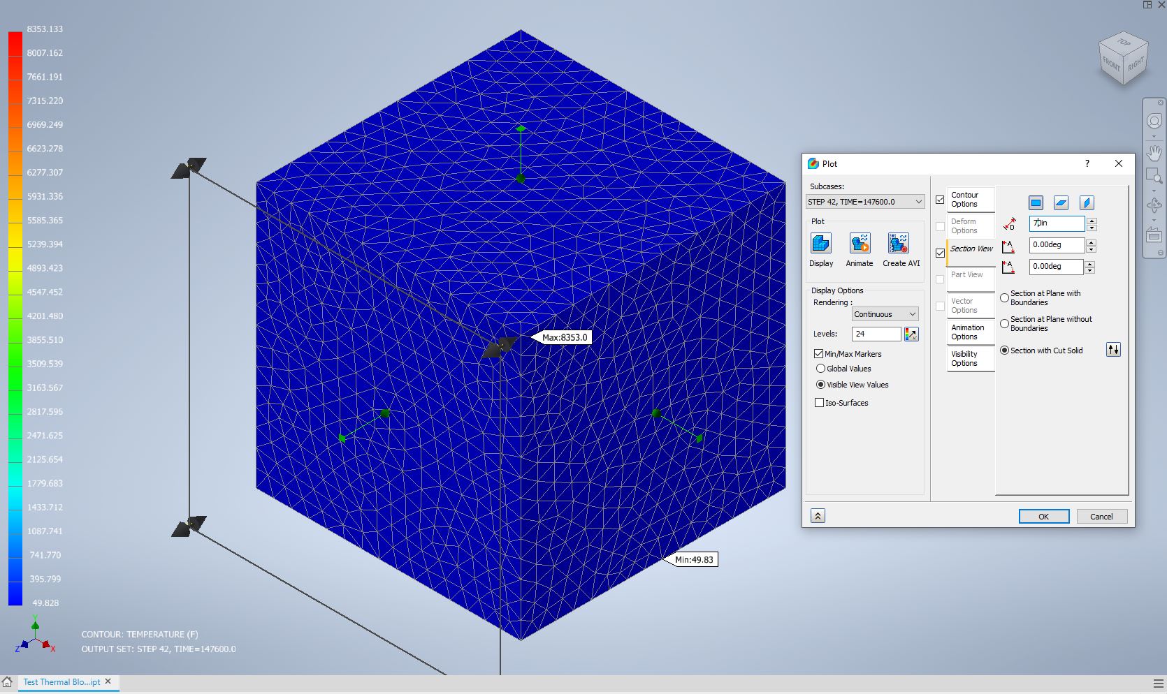
When I look at the global results, it tells me that the max temperature for the last time step is 2586 (again, I know the input values are unreasonable).  However, when I look at a section cut through the middle of the block, it tells me that the max temperature for the same time step is 8353.  Similarly, when I look at a section cut outside of the block such that the entire block is shown, it tells me that the max temperature is 8353.  (The min temperatures are shown as the same values in all three cases.)  Please see the pictures attached.


It shouldn't be the case that the max temperature is greater in the section view than in the global view.  Does anyone know what is going on or how to fix this?


I can provide the model if necessary.


Thanks,

Jonathan

0 Likes
1,718 Views
3 Replies
Replies (3)
Message 2 of 4

John_Holtz
Autodesk Support
Autodesk Support

Hi @jonathan.p.kelly 


This is just a guess based on the images. It looks like the maximum from the un-sectioned model is based on the nodes on the outside surface. (You can confirm if this is true by rotating the model around. Is the max marker on the outside? Or at best, it is the maximum from all of the nodes on the elements on the outside.) It probably does this for speed reasons, or because the nodes inside the model are not shown when the model is not sectioned.


It looks like that creating a section probably loads all of the nodes in anticipation of needing to show nodes/elements inside the model. If true, then the maximum is at the center of the volume (where it is hottest) regardless of where the section is. (Maybe if you cut away the middle of the volume, leaving only the outside 1/4, then maybe the max marker moves to the maximum temperature remaining "in view".)


John Holtz, P.E.

Global Product Support
Autodesk, Inc.


If not provided, indicate the version of Inventor Nastran you are using.
If the issue is related to a model, attach the model! See What files to provide when the model is needed.
0 Likes
Message 3 of 4

jonathan.p.kelly
Enthusiast
Enthusiast

Hi @John_Holtz,


I tried rotating the model around, and the max marker when not using the section view is not on the outside of the model.  Rather, the max marker is located like you can see in “Global View – Front.jpg”, in the center of the model horizontally, about 1/8 of the way down from the top surface.  Rotating the model 90 degrees so that you look at the Right side yields the same result, which means that the location of the identified max temperature is inside the model.  And, as it turns out, when I look at the section cut through the middle of the block, the temperature at the same depth into the model as where the global max marker is placed has roughly the same temperature as what is identified by the global max marker when not in section view.  This just isn’t the true max.


I looked at the other output values available (heat flux, thermal gradient, etc.), and they all produced expected results:  the max markers were consistent between section and global view.  So, the problem seems to be associated with the temperature.


I tried changing other values in the contour options and found, if I set the “Contour Type” to “Elemental” and check the box for “No Averaging”, then the max marker for the global view becomes the same as for the section view.  Unfortunately, this result is reversed when I change the settings back from Elemental with No Averaging.


Whatever the reason for not showing the true maximum temperature (speed, model complexity (though with only 5,029 nodes, this shouldn’t be the case), etc.), it is misleading and should be fixed.  You shouldn’t have to go to the extra effort of making a section cut to find the maximum value.  You should be able to have confidence that the original results are an accurate display of the model and the calculations performed (even if the model is not an accurate representation of reality).  And since this is an issue with displaying the results of an analysis, not with performing the analysis, it calls into question Nastran’s ability to display other results accurately.


I have attached the model (it’s just one part file) so that you or others can look into this further.


Thanks,

Jonathan

0 Likes
Message 4 of 4

John_Holtz
Autodesk Support
Autodesk Support

This is not definitive proof, but this view created with Simulation Mechanical implies that the node where the marker was shown (near the surface) is the deepest element attached to the surface. Therefore, I think my hypothesis is the reason for the behavior you noticed. To summarize,

  • When the model is not sectioned, all the results displayed are based on the nodes connected to the elements that have a face on the surface of the model. Elements with 1 node on the face of the model are not "included" in the results display.
  • When the model is sections, all the results displayed are based on all the nodes and all the elements.
  • For stress models, this is usually acceptable. The maximum stress is usually on the surface of the model. For heat transfer, the maximum result can be inside the volume, and therefore a section needs to be shown in order to "find" the maximum. (Likewise, thermal stress could have a maximum inside the volume. Hertz contact stress is another example of when the maximum stress is not necessarily on the surface.)

View from Simulation Mechanical. The elements on a "section" are shown close to where the "maximum" temperature marker was shown in Inventor Nastran. In this model with internal heat generation, the maximum temperature is expected to be at the center of the part, not near the surface.View from Simulation Mechanical. The elements on a "section" are shown close to where the "maximum" temperature marker was shown in Inventor Nastran. In this model with internal heat generation, the maximum temperature is expected to be at the center of the part, not near the surface.


This is not the definitive prove because it is only a "2D" section. The complete proof would need to look at all the elements on the surface of the model, but I cannot do that at this time.


John Holtz, P.E.

Global Product Support
Autodesk, Inc.


If not provided, indicate the version of Inventor Nastran you are using.
If the issue is related to a model, attach the model! See What files to provide when the model is needed.
0 Likes