Community
Inventor Forum
Welcome to Autodesk’s Inventor Forums. Share your knowledge, ask questions, and explore popular Inventor topics.
Turn on suggestions
Auto-suggest helps you quickly narrow down your search results by suggesting possible matches as you type.
Reply
Topic Options
- Subscribe to RSS Feed
- Mark Topic as New
- Mark Topic as Read
- Float this Topic for Current User
- Bookmark
- Subscribe
- Printer Friendly Page
Message 1 of 27
Anonymous
5517 Views, 26 Replies
04-23-2009
01:30 AM
- Mark as New
- Bookmark
- Subscribe
- Mute
- Subscribe to RSS Feed
- Permalink
- Report
04-23-2009
01:30 AM
stress analysis of a lifting lug
Good Morning.
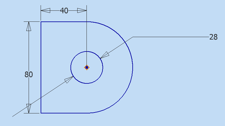
I am performing some analysis on a lug that will lift a 1000kg liner. The liner will be lifted by using the 28mm hole in the lug. As the liner will have to be upended fist the resulting forces will act in the X, Y and Z directions.
Do I do three different analysis for the lug in the X Y Z DIRECTIONS or can I just use the use "COMPONENTS FEATURE” to add a 10000N in each of the Fx Fy Fz directions. If I use the "COMPONENTS FEATURE" to add the 10000N in all directions will this result in an overall 30000N load. I have tried both and get different results for the maximum stress in the material. I have attached a copy of the lug.
Thanks, Paul
26 REPLIES 26
Message 2 of 27
04-23-2009
05:03 AM
- Mark as New
- Bookmark
- Subscribe
- Mute
- Subscribe to RSS Feed
- Permalink
- Report
04-23-2009
05:03 AM
I noticed that the circle in Sketch3 ??? was placed at the origin but not constrained to the origin. You might want to read this document before proceeding on to more complex topics like FEA.
http://home.pct.edu/~jmather/AU2007/MA105-1L%20Mather.pdf
Also you are missing a vertical or perpendicular constraint and you should indicate when you are not using the latest release, as you are likely to get solutions you can't open in an earlier release.
-----------------------------------------------------------------------------------------
Autodesk Inventor 2019 Certified Professional
Autodesk AutoCAD 2013 Certified Professional
Certified SolidWorks Professional
Message 3 of 27
Anonymous
in reply to:
Anonymous
04-23-2009
05:29 AM
- Mark as New
- Bookmark
- Subscribe
- Mute
- Subscribe to RSS Feed
- Permalink
- Report
04-23-2009
05:29 AM
The face I have constrained will get welded to the liner. Where else do I need to constrain? (vertical or perpendicular constraint )
Message 4 of 27
04-23-2009
05:53 AM
- Mark as New
- Bookmark
- Subscribe
- Mute
- Subscribe to RSS Feed
- Permalink
- Report
04-23-2009
05:53 AM
Sorry, I had not addressed your original question. My concern was basic modeling principles before advanced topics. My response was in reference to your first sketch (Sketch 3 ???).
>Where else do I need to constrain? (vertical or perpendicular constraint )
This only reinforces my concern.
I'm sure someone else will be along to answer your original question.
-----------------------------------------------------------------------------------------
Autodesk Inventor 2019 Certified Professional
Autodesk AutoCAD 2013 Certified Professional
Certified SolidWorks Professional
Message 6 of 27
Anonymous
in reply to:
Anonymous
04-23-2009
06:03 AM
- Mark as New
- Bookmark
- Subscribe
- Mute
- Subscribe to RSS Feed
- Permalink
- Report
04-23-2009
06:03 AM
go ahead and refer to that pdf JD mentioned.
The short of it is, when I open this ipt file (BTW, when have we been
able to attach Inventor part files without zipping them up first?!?!?)
The entire sketch was green indicating it was not fully constrained.
Once I dragged the sketch off of the Origin Center Point and applied a
coincident constraint between the center of the hole to the Origin
Center Point, I was able to see which line needed to have either a
vertical or perpendicular constraint as JD mentioned.
Give that a shot and see if you can figure it out.
But to reinterate, always practice fully constraining everything...it's
a good habit to get into.
Message 8 of 27
04-23-2009
06:08 AM
- Mark as New
- Bookmark
- Subscribe
- Mute
- Subscribe to RSS Feed
- Permalink
- Report
04-23-2009
06:08 AM
If you edit Sketch3 you will notice that you can click and drag an endpoint anywhere on the screen.
-----------------------------------------------------------------------------------------
Autodesk Inventor 2019 Certified Professional
Autodesk AutoCAD 2013 Certified Professional
Certified SolidWorks Professional
-----------------------------------------------------------------------------------------
Autodesk Inventor 2019 Certified Professional
Autodesk AutoCAD 2013 Certified Professional
Certified SolidWorks Professional
Message 9 of 27
04-23-2009
06:08 AM
- Mark as New
- Bookmark
- Subscribe
- Mute
- Subscribe to RSS Feed
- Permalink
- Report
04-23-2009
06:08 AM
If you edit Sketch3 and right click select Show all Degrees of Freedom notice the red arrows.
Edited by: JDMather on Apr 23, 2009 9:10 AM
-----------------------------------------------------------------------------------------
Autodesk Inventor 2019 Certified Professional
Autodesk AutoCAD 2013 Certified Professional
Certified SolidWorks Professional
-----------------------------------------------------------------------------------------
Autodesk Inventor 2019 Certified Professional
Autodesk AutoCAD 2013 Certified Professional
Certified SolidWorks Professional
Message 10 of 27
04-23-2009
06:16 AM
- Mark as New
- Bookmark
- Subscribe
- Mute
- Subscribe to RSS Feed
- Permalink
- Report
04-23-2009
06:16 AM
If I constrain the hole circle to the origin notice that the left line is not constrained. You need to add a vertical constraint to the line or you could add a perpendicular constraint between logical enitites.
-----------------------------------------------------------------------------------------
Autodesk Inventor 2019 Certified Professional
Autodesk AutoCAD 2013 Certified Professional
Certified SolidWorks Professional
-----------------------------------------------------------------------------------------
Autodesk Inventor 2019 Certified Professional
Autodesk AutoCAD 2013 Certified Professional
Certified SolidWorks Professional
Message 11 of 27
04-23-2009
06:19 AM
- Mark as New
- Bookmark
- Subscribe
- Mute
- Subscribe to RSS Feed
- Permalink
- Report
04-23-2009
06:19 AM
And in fact, if you constrain properly you need far fewer dimensions than you used in Sketch3.
-----------------------------------------------------------------------------------------
Autodesk Inventor 2019 Certified Professional
Autodesk AutoCAD 2013 Certified Professional
Certified SolidWorks Professional
-----------------------------------------------------------------------------------------
Autodesk Inventor 2019 Certified Professional
Autodesk AutoCAD 2013 Certified Professional
Certified SolidWorks Professional
Message 12 of 27
04-23-2009
06:25 AM
- Mark as New
- Bookmark
- Subscribe
- Mute
- Subscribe to RSS Feed
- Permalink
- Report
04-23-2009
06:25 AM
As few as 2 dimensions could be used to control the sketch.
-----------------------------------------------------------------------------------------
Autodesk Inventor 2019 Certified Professional
Autodesk AutoCAD 2013 Certified Professional
Certified SolidWorks Professional
-----------------------------------------------------------------------------------------
Autodesk Inventor 2019 Certified Professional
Autodesk AutoCAD 2013 Certified Professional
Certified SolidWorks Professional
Message 13 of 27
Anonymous
in reply to:
Anonymous
04-23-2009
06:30 AM
- Mark as New
- Bookmark
- Subscribe
- Mute
- Subscribe to RSS Feed
- Permalink
- Report
04-23-2009
06:30 AM
I do appreciate everyone’s responses and I fully understand the importance of constraining sketches and proper sketching methods as I have spent the last couple of years using SOLIDWORKS. INVENTOR is relatively new to me. If I edit Sketch3 and right click it is not showing me the degrees of freedom for some reason. If I don’t fully constrain the sketch will it have an effect on my stress analysis?
Paul
Paul
Message 14 of 27
04-23-2009
06:37 AM
- Mark as New
- Bookmark
- Subscribe
- Mute
- Subscribe to RSS Feed
- Permalink
- Report
04-23-2009
06:37 AM
>I have spent the last couple of years using SOLIDWORKS. INVENTOR is relatively new to me.
Read this one instead
http://home.pct.edu/~jmather/AU2006/MA13-3%20Mather.pdf
JD
Certified SolidWorks Professional
The SolidWorks sketch would be done the same as in Inventor. Usually covered in the first day of SWx training.
> If I edit Sketch3 and right click it is not showing me the degrees of freedom for some reason.
I forgot, you are using a much earlier release of Inventor. Did not exist in v11.
>If I don’t fully constrain the sketch will it have an effect on my stress analysis?
No, but I think there might be the same sort of basic FEA logic missing as was missing in first part sketch.
-----------------------------------------------------------------------------------------
Autodesk Inventor 2019 Certified Professional
Autodesk AutoCAD 2013 Certified Professional
Certified SolidWorks Professional
Message 15 of 27
Anonymous
in reply to:
Anonymous
04-23-2009
06:42 AM
- Mark as New
- Bookmark
- Subscribe
- Mute
- Subscribe to RSS Feed
- Permalink
- Report
04-23-2009
06:42 AM
stress analysis in Inventor is typically only for static loads, so I'm not certain that you can expect to achieve the dynamic lifting situation you're describing with the tools you have.
maybe use a bearing load on the hole in combination with moment loads???
I’m not an expert on this at all, maybe someone else who knows a bit more about this can provide some feedback on loading this accuratly
also i noticed this part is Inventor 11 SP2, you might consider an upgrade.
Version 11 was terrible compared to the versions that came after it.
At the very least consider installing the latest SP:
http://usa.autodesk.com/adsk/servlet/ps/dl/item?siteID=123112&id=11279159&linkID=9242019
hope this helps
Message 16 of 27
04-23-2009
06:45 AM
- Mark as New
- Bookmark
- Subscribe
- Mute
- Subscribe to RSS Feed
- Permalink
- Report
04-23-2009
06:45 AM
>stress analysis in Inventor is typically only for static loads
Dynamic Simulation. But I'm not sure that applies in this case if the load is intitially supported and only the analysis at full load is desired. Edited by: JDMather on Apr 23, 2009 9:46 AM
-----------------------------------------------------------------------------------------
Autodesk Inventor 2019 Certified Professional
Autodesk AutoCAD 2013 Certified Professional
Certified SolidWorks Professional
Message 17 of 27
Anonymous
in reply to:
Anonymous
04-23-2009
06:57 AM
- Mark as New
- Bookmark
- Subscribe
- Mute
- Subscribe to RSS Feed
- Permalink
- Report
04-23-2009
06:57 AM
My only concern was if the lug was loaded in the X Y Z directions at the same time. Would the "USE CONPONENT" take this into account spreading the 20000N accordingly in each direction or does it put a load of 60000N on the whole part hence my query about doing three different analysis.
Thanks, Paul
Thanks, Paul
Message 18 of 27
04-23-2009
07:05 AM
- Mark as New
- Bookmark
- Subscribe
- Mute
- Subscribe to RSS Feed
- Permalink
- Report
04-23-2009
07:05 AM
Calculating the xyz components of a resultant load is standard. With Dynamic Simulation (not available in r11) you could calculate at as many time steps in the motion from tilting the load to full lift as desired. (assuming I understand what you are trying to analyze)
-----------------------------------------------------------------------------------------
Autodesk Inventor 2019 Certified Professional
Autodesk AutoCAD 2013 Certified Professional
Certified SolidWorks Professional
-----------------------------------------------------------------------------------------
Autodesk Inventor 2019 Certified Professional
Autodesk AutoCAD 2013 Certified Professional
Certified SolidWorks Professional
Message 19 of 27
Anonymous
in reply to:
Anonymous
04-23-2009
07:16 AM
- Mark as New
- Bookmark
- Subscribe
- Mute
- Subscribe to RSS Feed
- Permalink
- Report
04-23-2009
07:16 AM
are you using Ansys, or Inventor Professional?
you keep referring to "USE CONPONENT", but I'm not familiar with that option in Inventor Professional. As I said, I'm not an expert, so I may be missing something.
you keep referring to "USE CONPONENT", but I'm not familiar with that option in Inventor Professional. As I said, I'm not an expert, so I may be missing something.
Message 20 of 27
Anonymous
in reply to:
Anonymous
04-23-2009
07:26 AM
- Mark as New
- Bookmark
- Subscribe
- Mute
- Subscribe to RSS Feed
- Permalink
- Report
04-23-2009
07:26 AM
I'm using Professional 11. If apply a load you can open up the dialogue box and it gives you the option. See attached.
Edited by: PAULPAULPAUL on Apr 23, 2009 2:27 PM
Reply
Topic Options
- Subscribe to RSS Feed
- Mark Topic as New
- Mark Topic as Read
- Float this Topic for Current User
- Bookmark
- Subscribe
- Printer Friendly Page
Forums Links
Can't find what you're looking for? Ask the community or share your knowledge.
Post to forums

