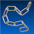
tangent between two curved srufaces

tangent between two curved srufaces

Anonymous
Not applicable
2,703 Views
7 Replies
Message 1 of 8

tangent between two curved srufaces

Anonymous
Not applicable

The tangent constraint between two curved surfaces in Inventor is very confusing. I have never been able to get the position I wanted.

For example, I would like to make a tangent contact between the two links as follows:

tangent-01.PNG


If I select the green and blue surfaces, the link will fly to this wierd position. I though the word "tangent" at least means two things are touching each other, why are the two surfaces driven further away??

tangent-02.PNG


If I select the other "solution"(internal tangent), this is what I get:

tangent-03.PNG


Keep clicking that button, the link can acutally fly around~~but none of the postions is "tangent" to the green surface

tangent-04.PNG tangent-05.PNG tangent-06.PNGtangent-07.PNG


If someone can provide a detailed explanation of this tangent constraint, and tell me how to make it right, I'll be very grateful.


0 Likes
Accepted solutions (1)
2,704 Views
7 Replies
Replies (7)
Message 2 of 8

blair
Mentor
Mentor
Accepted solution

You actually have 2 tangents for each end of the loop. The first is the solid and the second is the swept path. I've never been able to get the tangent to work properly when putting together a looped chain with links.


I end up resorting to creating work points and using them. Smiley Sad

Spoiler
 

Inventor 2020, In-Cad, Simulation Mechanical

Just insert the picture rather than attaching it as a file
Did you find this reply helpful ? If so please use the Accept as Solution or Kudos button below.
Delta Tau Chi ΔΤΧ

Message 3 of 8

SBix26
Consultant
Consultant

Constraints are geometric mathematical constructs, not reality.  Surfaces participating in a constraint are considered to be geometric entities.  For example a flat face of a part, for constraint purposes, is a plane, infinite in all directions.  In the same way, these half loop faces are actually circular tori (plural of torus) for constraint purposes, so what you are seeing is mathematically accurate, just not very helpful in making this behave like real solid objects.


I would do as Blair suggested and use some other geometry to help constrain them (angles with limits, work points, origin planes, etc.).  For a closer simulation of real-world behavior, you can use contact sets, but they are computationally intensive and make Inventor sweat (mathematically speaking, of course).  Contact sets do not take into account friction and gravity, so are still not as much like the material world as we would like.


Disclaimer: this is all just my observation and deduction from thirteen years of Inventor use, not because I have any inside knowledge!


Hope that helps,

Sam B

Inventor Professional 2016 R3 SP2
Vault Basic 2016 SP1
Windows 7 Enterprise 64-bit, SP1
Autodesk_Inventor_Certified_Professional_Badge.png

Message 4 of 8

TheCADWhisperer
Consultant
Consultant

What is your ultimate design intent?


You might need to progress over into Environments>Dynamic Simulation if it is more than simple assembly.

0 Likes
Message 5 of 8

Curtis_Waguespack
Consultant
Consultant

H iziyin.w,


It's beem a long time since I looked at this model, but cbliss.com has chain example that you might look at, if you've not already done so.


I hope this helps.
Best of luck to you in all of your Inventor pursuits,
Curtis
http://inventortrenches.blogspot.com


Click thumbnail to open a zip file:


wpe8.jpg (3830 bytes)


Message 6 of 8

Anonymous
Not applicable

Thank you all for your kind suggestions. So I'll mark it as a "no-shortcut" problem in Inventor.


Thank you Curtis for the chain example, it's beautifully modelled. And your blog is fantastic!

0 Likes
Message 7 of 8

Anonymous
Not applicable
Hello, I have tried to understand how did the author do the mate constrains between the chain links, but I couldn't. And what is the purpose of the angle constrain and how did he place it? Thankyou atajabbas Inventor 2020
0 Likes
Message 8 of 8

johnsonshiue
Community Manager
Community Manager

Hi Folks,


Let me elaborate on the Tangent constraint behavior a bit here. Inventor assembly Tangent constraint actually operates on the base faces. For example, the tangent target faces are two half torodial faces. What is being solved is the full torodial face. So, it may look odd as if the faces are constrained in the air. The behavior is meant to make Tangent less restrictive.

Many thanks!


Johnson Shiue ([email protected])
Software Test Engineer