Community
- Forums Home
- >
- Inventor Community
- >
- Inventor Forum
- >
- Re: Sheet metal elbow pipe - how to cut it in half and unfold it?
Inventor Forum
Welcome to Autodesk’s Inventor Forums. Share your knowledge, ask questions, and explore popular Inventor topics.
Turn on suggestions
Auto-suggest helps you quickly narrow down your search results by suggesting possible matches as you type.
Reply
Topic Options
- Subscribe to RSS Feed
- Mark Topic as New
- Mark Topic as Read
- Float this Topic for Current User
- Bookmark
- Subscribe
- Printer Friendly Page
Message 1 of 8
08-13-2019
02:24 AM
- Mark as New
- Bookmark
- Subscribe
- Mute
- Subscribe to RSS Feed
- Permalink
- Report
08-13-2019
02:24 AM
Sheet metal elbow pipe - how to cut it in half and unfold it?
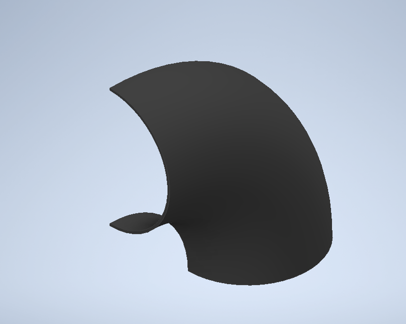
Hello - first of all, I'm semi new to Inventor - it's an amazing program I'm using since I needed something with importable(?) parameters into BOM's opposed to Fusion 360. I love this program. That being said, there's still a lot I don't know how to do. Currently I'm trying to make a bent pipe (half of it) in sheet metal so I can unfold it and see what I need to cut before I press it. English is not my native language so here's some pictures of what I need to do:
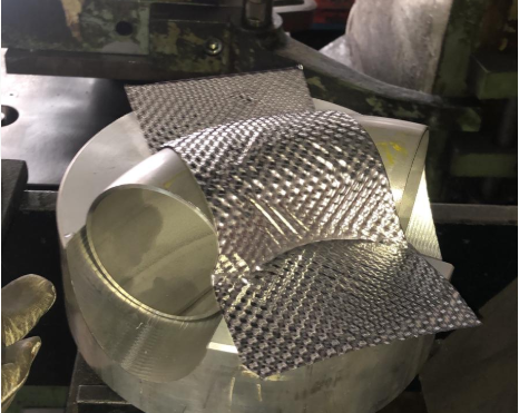
I apologize for lack of clarity, I really don't know how to explain this in english so I hope pictures help. Now usually the way I make pipes is I create an arc with specific radius and angle, then make a profile and use the sweep tool. I never used the sheet metal part, but I did find some tutorials on how to make cylinders using contour roll - that's exactly what I need, but I don't know how to make an axis that's 'bent' like the pipe I need. I have found a way to create the sheet metal elbow part with a 1mm slot between to not have a closed profile, but now I don't know how to cut it in half and unfold it. I've attached the file I've made.
The desired values for the 'shell' around the pipe are 82mm in diameter on a 98mm radius.
Thank you for any input on the matter, good day!
7 REPLIES 7
Message 2 of 8
08-13-2019
04:14 AM
- Mark as New
- Bookmark
- Subscribe
- Mute
- Subscribe to RSS Feed
- Permalink
- Report
08-13-2019
04:14 AM
Hi, have you tried using the unwrap command in Inventor 2020?
I have Inventor 2018, so I can't try to reach a flattening of the surface. You cannot achieve a flatPattern in the conventional way.
I hope this helps. regards
Please accept as solution and give likes if applicable.
I am attaching my Upwork profile for specific queries.
Sergio Daniel Suarez
Mechanical Designer
| Upwork Profile | LinkedIn
Message 3 of 8
08-13-2019
04:50 AM
- Mark as New
- Bookmark
- Subscribe
- Mute
- Subscribe to RSS Feed
- Permalink
- Report
08-13-2019
04:50 AM
As suggested by @Sergio.D.Suárez , try adjusting the parameters in Unwrap and see if you get a "close enough" result.

-----------------------------------------------------------------------------------------
Autodesk Inventor 2019 Certified Professional
Autodesk AutoCAD 2013 Certified Professional
Certified SolidWorks Professional
Message 4 of 8
08-13-2019
04:52 AM
- Mark as New
- Bookmark
- Subscribe
- Mute
- Subscribe to RSS Feed
- Permalink
- Report
08-13-2019
04:52 AM
To put it simply, Inventor sheet metal at this point can only provide accurate flat patterns of parts formed by brake press and straight roller, any forming that stretches the material in more than one direction at once typically cannot be flattened without problems getting in the way. The unwrap method as Sergio and Mather suggested is your next option.
Message 5 of 8
08-13-2019
05:52 AM
- Mark as New
- Bookmark
- Subscribe
- Mute
- Subscribe to RSS Feed
- Permalink
- Report
08-13-2019
05:52 AM
Thank you all for replying.
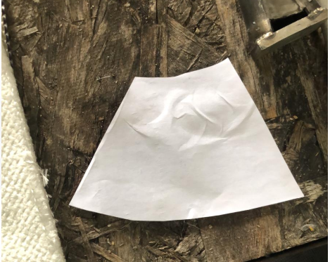
Unwrap created some weird results, using rigid frame on the lower arc it made everything too big:
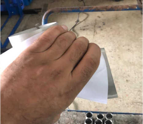
Without the rigid edge it created something resembling what I need: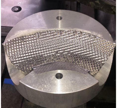
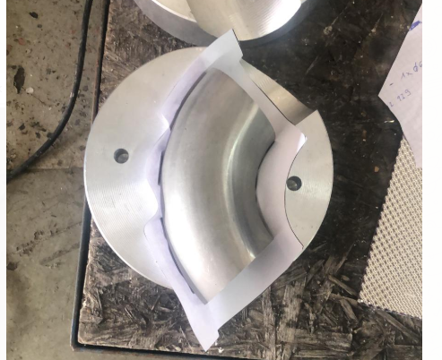
though as you can see there's way too much material on lower arc and a bit too little on the upper arc. Now I'm trying to get the 'flat pattern' to work, but when I create a flat pattern from something like this:
it makes literally a rectangle material:
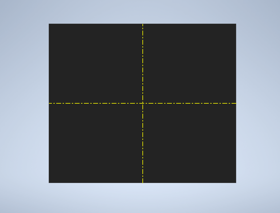
I've attached a file of the sheet metal part I'm trying to use flat pattern on, maybe there's something I didn't tick? Or is it normal behaviour and I can't get it to 'flatten' the part?
Message 6 of 8
08-13-2019
06:51 AM
- Mark as New
- Bookmark
- Subscribe
- Mute
- Subscribe to RSS Feed
- Permalink
- Report
08-13-2019
06:51 AM
You will not get a correct flat pattern of that part.
-----------------------------------------------------------------------------------------
Autodesk Inventor 2019 Certified Professional
Autodesk AutoCAD 2013 Certified Professional
Certified SolidWorks Professional
Message 7 of 8
08-13-2019
07:30 AM
- Mark as New
- Bookmark
- Subscribe
- Mute
- Subscribe to RSS Feed
- Permalink
- Report

Message 8 of 8
08-13-2019
03:42 PM
- Mark as New
- Bookmark
- Subscribe
- Mute
- Subscribe to RSS Feed
- Permalink
- Report
08-13-2019
03:42 PM
Hi! The rectangular flat pattern is a representation of an unrolled elbow. The rolled (Contour Roll) shape created in Inventor Sheet Metal is meant for keeping the unfold length of linear extensions on both ends intact. The roll itself is not meant to be flattened.
Many thanks!
Johnson Shiue (johnson.shiue@autodesk.com)
Software Test Engineer
Reply
Topic Options
- Subscribe to RSS Feed
- Mark Topic as New
- Mark Topic as Read
- Float this Topic for Current User
- Bookmark
- Subscribe
- Printer Friendly Page
Forums Links
Can't find what you're looking for? Ask the community or share your knowledge.
Post to forums

