Community
Inventor Forum
Welcome to Autodesk’s Inventor Forums. Share your knowledge, ask questions, and explore popular Inventor topics.
Turn on suggestions
Auto-suggest helps you quickly narrow down your search results by suggesting possible matches as you type.
Reply
Topic Options
- Subscribe to RSS Feed
- Mark Topic as New
- Mark Topic as Read
- Float this Topic for Current User
- Bookmark
- Subscribe
- Printer Friendly Page
Message 1 of 5
Anonymous
1162 Views, 4 Replies
01-04-2013
02:36 AM
- Mark as New
- Bookmark
- Subscribe
- Mute
- Subscribe to RSS Feed
- Permalink
- Report
01-04-2013
02:36 AM
Modelling a cable
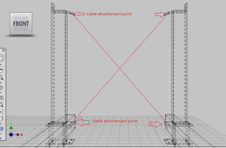
I was wondering the best way to model a steel tensioner cable in Inventor. The assembly I have designed is of a cable fixed between two brackets which are fastened on two structural beams. I am looking accurately model the cable attachment on the brackets. My inital thought would be to extrude the length of cable through a pre-defined path between the bracket fixing holes however this would not represent a 'true life scenario'. Any suggestions would be appreciated.
Product Design Suite Ultimate 2013
64-bit HP Z400, Intel Xeon W3550 3.07GHz
12.0GB RAM, ATI FirePro V4800 (FireGL)
4 REPLIES 4
Message 2 of 5
01-04-2013
03:42 AM
- Mark as New
- Bookmark
- Subscribe
- Mute
- Subscribe to RSS Feed
- Permalink
- Report
01-04-2013
03:42 AM
Post a picture of what you're trying to accomplish. You call it a tensioner cable, which leads me to think that it will mostly be straight (i.e. under tension), so I'm not understanding the "true life scenario".
Message 3 of 5
01-04-2013
04:21 AM
- Mark as New
- Bookmark
- Subscribe
- Mute
- Subscribe to RSS Feed
- Permalink
- Report
01-04-2013
04:21 AM
@Anonymous wrote:...extrude the length of cable through a pre-defined path
That describes Sweep, not Extrude.
-----------------------------------------------------------------------------------------
Autodesk Inventor 2019 Certified Professional
Autodesk AutoCAD 2013 Certified Professional
Certified SolidWorks Professional
Message 4 of 5
01-04-2013
05:36 AM
- Mark as New
- Bookmark
- Subscribe
- Mute
- Subscribe to RSS Feed
- Permalink
- Report
01-04-2013
05:36 AM
Hi, thank you for your reply. Please see attached screenshot of the intended result. The cables will be under tension as you have stated and will therefore will be represented straight, I may be asked to produce flexible cable as well for further design development which is why I asked the original question. Thank you.
Message 5 of 5
01-06-2013
09:59 PM
- Mark as New
- Bookmark
- Subscribe
- Mute
- Subscribe to RSS Feed
- Permalink
- Report
01-06-2013
09:59 PM
Hi
The Cable is not the problem here, simple extrude/sweep, the issue is the attachments.
You will need to model up the fittings and tensioner (Shackles, rigging screws, Swage ends, etc) Have a look at "VanBeest" there are a lot of fixings there (All green pin lifting equipment), the rest you will have to look at grabcad, and do your own modeling.
This will give you a better representation of the cable.
Reg
2025.1.2
Please Accept as a solution / Kudos
2025.1.2
Please Accept as a solution / Kudos
Reply
Topic Options
- Subscribe to RSS Feed
- Mark Topic as New
- Mark Topic as Read
- Float this Topic for Current User
- Bookmark
- Subscribe
- Printer Friendly Page
Forums Links
Can't find what you're looking for? Ask the community or share your knowledge.
Post to forums
