

- Mark as New
- Bookmark
- Subscribe
- Mute
- Subscribe to RSS Feed
- Permalink
- Report
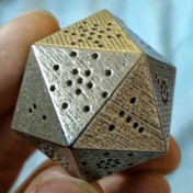
We make a piece that has a bunch of sideways "H"-shaped cuts in it, like pictured below.

However, we make these cuts with a waterjet, which means we essentially want them to be zero-width (lines), because otherwise the waterjet will trace BOTH sides of the cut, which isn't necessary and doubles the production time.
But I haven't been able to find a way to do this in Inventor. I can't even make that shape of cut using the Split tool, and even if I could, we can't pattern a Split in Inventor.
I tried using the Sheet Metal environment to make a rectangular cut and then create the two flaps as straight Flanges, and I could almost get this to work, but I couldn't get the top/bottom gap to be zero, and the two flanges would always fuse together in the middle.
We need this part in our Inventor assembly for visual purposes, plus it's parametrically connected to other parts of the design; so modeling it in Inventor is not optional. But we'd really like to avoid having to re-draw it all over again in AutoCAD just for the waterjet drawing. Not only is this a pain, it also results in wasted time, potential for mistakes, and/or project delays.
We'd like a solution where we can either:
A) Model the part with zero-width cuts in Inventor (preferred), or
B) Export the Inventor model with finite-width-cuts like we have to make now, and somehow auto-magically convert them to zero-width cuts (lines) in AutoCAD
Any suggestions are appreciated.
Solved! Go to Solution.