How do I emboss/extrude all at once?

How do I emboss/extrude all at once?

EndlessStruggler
Contributor Contributor
1,650 Views
31 Replies
Message 1 of 32

How do I emboss/extrude all at once?

EndlessStruggler
Contributor
Contributor

Hi,


I'm rather new to Autodesk Inventor, but I'm trying to create an arm sleeve with small round circular parts that provide vibrations when used. I have made circles on about the whole sleeve. The problem is when I extrude or emboss, I'm only able to do it with one circle, not with the inner circles or the other ones. When I complete one circle, the rest all disappear. I previously had to duplicate and arrange every circle and doing it again for embossing or engraving is going to be a nightmare. 


What's the best way to go about completing this?

0 Likes
Accepted solutions (3)
1,651 Views
31 Replies
Replies (31)
Message 2 of 32

JDMather
Consultant
Consultant

@EndlessStruggler wrote:

1. When I complete one circle, the rest all disappear. 


2. What's the best way to go about completing this?


There are several improvements possible for this technique.

1. Please Attach this *.ipt file here 

You could simply click on the sketch after creating the first feature and turn Visibility back on. Problem solved!

2. But you are doing too much work.  The best way to go about completing this is to Pattern features, not sketch elements.


Attach your file here and end all doubt.


-----------------------------------------------------------------------------------------
Autodesk Inventor 2019 Certified Professional
Autodesk AutoCAD 2013 Certified Professional
Certified SolidWorks Professional


0 Likes
Message 3 of 32

EndlessStruggler
Contributor
Contributor

Thanks for replying. 

I see, patterning elements. I'm not too familiar with that but I have attached my file here. 


0 Likes
Message 4 of 32

89198826955
Collaborator
Collaborator

Option 1: Sharing a SketchБезымянный.jpgoption 2: array of elements

Снимок3.PNG

Message 5 of 32

JDMather
Consultant
Consultant

@EndlessStruggler wrote:

When I complete one circle, the rest all disappear.


@EndlessStruggler 

You didn't Attach the requested file?

In the file that you Attached all of the circles are visible - none of them have disappeared?


I don't see any dimensions on the circles?  What size are the circles?  Where is the first circle (exact position)?


-----------------------------------------------------------------------------------------
Autodesk Inventor 2019 Certified Professional
Autodesk AutoCAD 2013 Certified Professional
Certified SolidWorks Professional


0 Likes
Message 6 of 32

EndlessStruggler
Contributor
Contributor

None of them have disappeared but when I perform the extrude/emboss action they do. I have undid that so that they're all here in hopes of finding a more efficient way of getting this task done. The first circle is in the top left. The outer circle is 8mm in diameter, the middle circle is 4.472mm and the inner circle is 2mm.

0 Likes
Message 7 of 32

JDMather
Consultant
Consultant

You are missing the point.

How is anyone supposed to know what you are doing with the circles if you undo what you did? Attach the actual problem file.  This doesn’t have to be an endless struggle.


And dimension your geometry. Without dimensions you are missing the power of parametric modeling.


-----------------------------------------------------------------------------------------
Autodesk Inventor 2019 Certified Professional
Autodesk AutoCAD 2013 Certified Professional
Certified SolidWorks Professional


0 Likes
Message 8 of 32

EndlessStruggler
Contributor
Contributor

Okay, here is the problem file.

0 Likes
Message 9 of 32

JDMather
Consultant
Consultant

@EndlessStruggler wrote:

The problem is when I extrude or emboss,


This feature should be done as an Extrude, not as Emboss.

What happens if you right click on the sketch in the browser (drill down into Emboss) and select Share Sketch?

JDMather_0-1681127068279.png


-----------------------------------------------------------------------------------------
Autodesk Inventor 2019 Certified Professional
Autodesk AutoCAD 2013 Certified Professional
Certified SolidWorks Professional


0 Likes
Message 10 of 32

JDMather
Consultant
Consultant

@EndlessStruggler 

What manufacturing process/inspection device will be used to 

JDMather_0-1681127181451.png

create/measure a feature of Ø4.472136?


-----------------------------------------------------------------------------------------
Autodesk Inventor 2019 Certified Professional
Autodesk AutoCAD 2013 Certified Professional
Certified SolidWorks Professional


0 Likes
Message 11 of 32

JDMather
Consultant
Consultant

@EndlessStruggler 

Why not use Extrude and simply click and drag a selection window over all circles?

JDMather_0-1681127354119.png


-----------------------------------------------------------------------------------------
Autodesk Inventor 2019 Certified Professional
Autodesk AutoCAD 2013 Certified Professional
Certified SolidWorks Professional


0 Likes
Message 12 of 32

JDMather
Consultant
Consultant
Accepted solution

@EndlessStruggler 

Better yet, why not sketch only one set of concentric circles, Extrude and then Pattern?

JDMather_0-1681127542082.pngJDMather_1-1681127656731.png


-----------------------------------------------------------------------------------------
Autodesk Inventor 2019 Certified Professional
Autodesk AutoCAD 2013 Certified Professional
Certified SolidWorks Professional


Message 13 of 32

CStilesCARE
Advocate
Advocate
Accepted solution

Hey @EndlessStruggler !


It sounds like a lot of the issues you're having are related to understanding some of the basics of how Inventor works, and there's no harm in that. After all, we all start somewhere!


The issue with the sketch disappearing is actually by-design. In many cases, features are created based on a "1 sketch, 1 feature" basis, so Inventor hides them once they've been used so it doesn't clutter up the view really quickly.

If you look in the model browser tree though, you can click on the feature node to expand it and show the hidden sketch and make it visible again.


@JDMather mentioned that in one of his replies. He's a master with Inventor and has a ton of knowledge and great things to teach.


Some of what he said can be boiled down to the below (plus my own 2-cents) about how to model stuff.

  1. Be accurate, and don't leave loose ends.
    • This doesn't necessarily mean lots of decimal places. It just means to constrain and dimension everything, so there's no unintended "wiggle room".
      • Think about how the part will be, and use the origin features thoughtfully (you can project them into sketches and constrain to them!), perhaps so the part can be easily constrained with them in an assembly later.
      • Use geometric constraints for everything that makes sense, and create dimensions for the rest. Nothing should be free to move when you're done with a sketch unless you have a specific reason to do so.
      • When creating dimensions, use numbers that make sense (maybe round numbers or specific fractions), and don't be afraid to let Inventor do the math instead of you! Use manually-placed numbers where they're needed, and use the power of parametric constraints and expressions to make Inventor solve other bits.
  2. Be smart about being lazy.
    • It's not about not doing the required work. It's about doing what is needed in the most efficient way, and using the tools that are best-suited to help you get there.
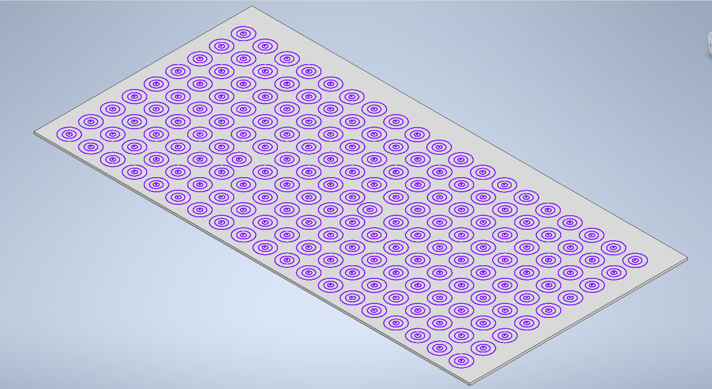
      • For example, Inventor is great at creating patterns, especially for features (and has more workflows for them compared to patterns within sketches). Don't draw all that stuff manually. Do the first one, then make Inventor do the rest of the work for you!
    • Inventor has a great number of tools and commands, and many of them seem like they do very similar things. Pay close attention to those ones especially and don't be afraid to hit that F1 key to learn more about them. Those minor differences are there for a reason and choosing the right one can save you a lot of time later on if you learn where each one shines.  A few examples:
      • Even though you can just "EXTRUDE" a circle to create a hole, there are very good reasons to use the "HOLE" feature instead. Even though it may actually take a few more clicks to do, it can set you up for huge time savings later on in the assembly and drawing phases.
      • Creating a single feature (like a hole) and then creating a PATTERN of it will enable you to reference that pattern at the assembly level automatically (say, for installing bolts into the patterned holes), saving you from having to place them manually.
      • In SHEET METAL parts, using the specific commands like "FACE" and "CUT" enable powerful options to work with constant-thickness parts (like cutting normal to thickness or wrapping around bends) that don't exist if you just use "extrude".
Message 14 of 32

EndlessStruggler
Contributor
Contributor

Thank you so much JDMather!


I didn't know how to pattern it properly

0 Likes
Message 15 of 32

EndlessStruggler
Contributor
Contributor

Yes, that's right. I'm completely new and wasn't sure of the patterning tool.


Thank you CStilesCARE for your insight and tips and to JDMather for showing me visually what he has done. I really appreciate your time and support.

0 Likes
Message 16 of 32

JDMather
Consultant
Consultant

@EndlessStruggler 


What were the concentric circles for?

I recommend that you continue on using those circles for whatever features you intended to create and then post back with more questions.


-----------------------------------------------------------------------------------------
Autodesk Inventor 2019 Certified Professional
Autodesk AutoCAD 2013 Certified Professional
Certified SolidWorks Professional


0 Likes
Message 17 of 32

JDMather
Consultant
Consultant

@EndlessStruggler wrote:

I'm trying to create an arm sleeve


@EndlessStruggler 

Is the Design Intent for these to be on a plane?


-----------------------------------------------------------------------------------------
Autodesk Inventor 2019 Certified Professional
Autodesk AutoCAD 2013 Certified Professional
Certified SolidWorks Professional


0 Likes
Message 18 of 32

EndlessStruggler
Contributor
Contributor

The concentric circles were added in to provide for greater sensitivity when using the product

0 Likes
Message 19 of 32

EndlessStruggler
Contributor
Contributor

Yes, the design intent was for them to be on a plane

0 Likes
Message 20 of 32

JDMather
Consultant
Consultant

@EndlessStruggler wrote:

The concentric circles were added in to provide for greater sensitivity when using the product


Why didn't you end up using them?


-----------------------------------------------------------------------------------------
Autodesk Inventor 2019 Certified Professional
Autodesk AutoCAD 2013 Certified Professional
Certified SolidWorks Professional


0 Likes