Community
Inventor Forum
Welcome to Autodesk’s Inventor Forums. Share your knowledge, ask questions, and explore popular Inventor topics.
Turn on suggestions
Auto-suggest helps you quickly narrow down your search results by suggesting possible matches as you type.
Reply
Topic Options
- Subscribe to RSS Feed
- Mark Topic as New
- Mark Topic as Read
- Float this Topic for Current User
- Bookmark
- Subscribe
- Printer Friendly Page
Message 1 of 21
Anonymous
37361 Views, 20 Replies
05-17-2011
10:06 AM
- Mark as New
- Bookmark
- Subscribe
- Mute
- Subscribe to RSS Feed
- Permalink
- Report
05-17-2011
10:06 AM
I need to calculate the change in moment of intertia due to modifing a simple angled beam from 120 x 120 x 10 to 120 x 112 x 10. Inventor has a function for moments but it rotates the center plane to something like VxV in the link below. Is there a way to calculate this to X-X? The instructions on this function are not very clear to me. I'm also no expert with Inventor. Thanks
http://www.roymech.co.uk/Useful_Tables/Sections/Angles_dim_prop.htm
Solved! Go to Solution.
20 REPLIES 20
Message 2 of 21
Anonymous
in reply to:
Anonymous
05-18-2011
12:56 AM
- Mark as New
- Bookmark
- Subscribe
- Mute
- Subscribe to RSS Feed
- Permalink
- Report
05-18-2011
12:56 AM
do it in sketch mode, click tools, measure, region properties then calculate...
I only touched on this yesterday and would be interested if there was a better way, say properties of a boundry patch or similar
Message 3 of 21
05-18-2011
04:38 AM
- Mark as New
- Bookmark
- Subscribe
- Mute
- Subscribe to RSS Feed
- Permalink
- Report
05-18-2011
04:38 AM
Something like this? (see attached)
-----------------------------------------------------------------------------------------
Autodesk Inventor 2019 Certified Professional
Autodesk AutoCAD 2013 Certified Professional
Certified SolidWorks Professional
Message 6 of 21
Anonymous
in reply to:
Anonymous
11-06-2014
01:29 AM
- Mark as New
- Bookmark
- Subscribe
- Mute
- Subscribe to RSS Feed
- Permalink
- Report
11-06-2014
01:29 AM
The same problem here:
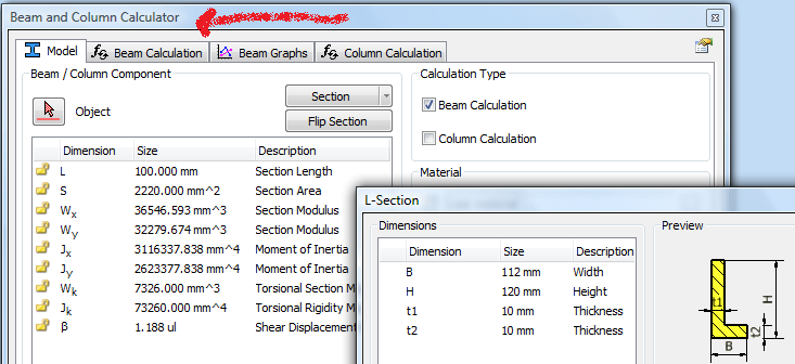
I have to calculate profile's Moment of inertia and resistance in X and Y directions, with given parameters like this:
.JPG")
Inventor Region properties gives such results:

Area is correct, but the rest isn't (comparing to the table).
I think the problem is with the centroid - the X and Y zero points are slightly shifted in the original calculations.
Is it possible to carry out such calculations with moved centre point in Inventor?
Message 7 of 21
Anonymous
in reply to:
Anonymous
04-03-2017
03:03 AM
- Mark as New
- Bookmark
- Subscribe
- Mute
- Subscribe to RSS Feed
- Permalink
- Report
04-03-2017
03:03 AM
HI,
Can MOI be measured for a 3d shape?
I design and make cricket bats and am keen to calculate the changes of MOI on different shapes.
Thanks in advance,
David
Message 8 of 21
Anonymous
in reply to:
Anonymous
01-01-2018
10:31 PM
- Mark as New
- Bookmark
- Subscribe
- Mute
- Subscribe to RSS Feed
- Permalink
- Report
01-01-2018
10:31 PM
Hi David,
With your question, yes, MOI can be measured both for 2D and 3D shape. You can try using 2 Moment of Inertia calculator, one is from skyciv the other one is from autodesk, it's also free. Have a look https://www.autodesk.com/education/free-software/featured.
Both of them are good resources.
Hope it helps.
Good luck!
C.
Message 9 of 21
10-15-2018
07:52 PM
- Mark as New
- Bookmark
- Subscribe
- Mute
- Subscribe to RSS Feed
- Permalink
- Report
10-15-2018
07:52 PM
I have noticed that the region properties only calculate correctly when the sketch is located on the XY plane.
Message 10 of 21
11-07-2018
06:33 AM
- Mark as New
- Bookmark
- Subscribe
- Mute
- Subscribe to RSS Feed
- Permalink
- Report
11-07-2018
06:33 AM
@Kai.Farrar wrote:I have noticed that the region properties only calculate correctly when the sketch is located on the XY plane.
Is this true?
Message 11 of 21
11-07-2018
02:10 PM
- Mark as New
- Bookmark
- Subscribe
- Mute
- Subscribe to RSS Feed
- Permalink
- Report
11-07-2018
02:10 PM
Hi Andrew,
I don't think that is true. We do have bugs in Regional Properties but it is not about calculation on different sketch planes. It should work in any 2D sketch regardless of the plane. I will need to see an example showing otherwise.
Many thanks!
Johnson Shiue (johnson.shiue@autodesk.com)
Software Test Engineer
Message 12 of 21
11-08-2018
10:35 AM
- Mark as New
- Bookmark
- Subscribe
- Mute
- Subscribe to RSS Feed
- Permalink
- Report
11-08-2018
10:35 AM
I have attached screen shots of identical areas drawn on different planes.
The one drawn on the XY plane is correct.
The one drawn on the ZY plane is backward.
The centroid location is wrong too.
@johnsonshiue wrote:Hi Andrew,
I don't think that is true. We do have bugs in Regional Properties but it is not about calculation on different sketch planes. It should work in any 2D sketch regardless of the plane. I will need to see an example showing otherwise.
Many thanks!


Message 13 of 21
11-08-2018
05:09 PM
- Mark as New
- Bookmark
- Subscribe
- Mute
- Subscribe to RSS Feed
- Permalink
- Report
11-08-2018
05:09 PM
Hi Kai,
I cannot seem to reproduce it on 2019.2. The images you shared indeed are wrong. What release are you on?
Many thanks!
Johnson Shiue (johnson.shiue@autodesk.com)
Software Test Engineer
Message 14 of 21
11-08-2018
05:13 PM
- Mark as New
- Bookmark
- Subscribe
- Mute
- Subscribe to RSS Feed
- Permalink
- Report
Message 15 of 21
11-08-2018
05:19 PM
- Mark as New
- Bookmark
- Subscribe
- Mute
- Subscribe to RSS Feed
- Permalink
- Report
11-08-2018
05:19 PM
Hi Kai,
Attached is the file I created based on the image. It seems to work fine for me on 2019.2. Do you mind sharing a file showing the problem?
Many thanks!
Johnson Shiue (johnson.shiue@autodesk.com)
Software Test Engineer
Message 16 of 21
11-09-2018
10:33 AM
- Mark as New
- Bookmark
- Subscribe
- Mute
- Subscribe to RSS Feed
- Permalink
- Report
11-09-2018
10:33 AM
I get the same bad results with your file as when I create my own.
Is there a setting or something that is messing this up?


Message 17 of 21
11-09-2018
01:04 PM
- Mark as New
- Bookmark
- Subscribe
- Mute
- Subscribe to RSS Feed
- Permalink
- Report
11-09-2018
01:04 PM
Hi Kai,
I think I know the difference. Go to Tools -> Application Options -> General -> Physical properties. You probably have "Calculate inertial properties using negative integral" option unchecked. Mine is checked by default.
Below is an excerpt of the option and how it works.
https://help.autodesk.com/view/INVNTOR/2019/ENU/?guid=GUID-A8E50133-E4FF-4459-B2AE-9568D2C9F565
Calculate inertial properties using the negative integral
Controls how the inertial properties are reported in the Properties dialog box Physical tab, and on the clipboard.
When selected, the negative integral, and either the Global or Center of Gravity is selected in the Properties dialog box, Physical tab, Inertial Properties section. The data shown is the rigid body inertia tensor of the selected component. Any of the off diagonal elements (Ixy, Iyz, Ixz) can be negative or positive, depending on the coordinate system and the component mass distribution.
When cleared, the positive integral flips the sign of the off diagonal elements to report only the integral part of the value.
Many thanks!
Johnson Shiue (johnson.shiue@autodesk.com)
Software Test Engineer
Message 18 of 21
11-09-2018
01:12 PM
- Mark as New
- Bookmark
- Subscribe
- Mute
- Subscribe to RSS Feed
- Permalink
- Report
11-09-2018
01:12 PM
That is checked for me too.
I unchecked it and calculated the region properties of the 5x10 rectangles again and got the same results.

Message 19 of 21
09-25-2020
10:44 AM
- Mark as New
- Bookmark
- Subscribe
- Mute
- Subscribe to RSS Feed
- Permalink
- Report
09-25-2020
10:44 AM
Looks like 2019 at least you can do Inspect->Analysis->Section
for a Cross Section Analysis! (Make sure to do the Advanced one).
P.Eng. Mechanical Engineer
Dell Precision 5680 Laptop; Win11 Pro; 64GB RAM; i9-13900H CPU; Intel Iris Xe Graphics, NVIDIA RTX 3500 Ada Laptop GPU.
Vault Pro 2025.1 (30.1.63.0); Inventor Pro 2025.1.1 (241).
Dell Precision 5680 Laptop; Win11 Pro; 64GB RAM; i9-13900H CPU; Intel Iris Xe Graphics, NVIDIA RTX 3500 Ada Laptop GPU.
Vault Pro 2025.1 (30.1.63.0); Inventor Pro 2025.1.1 (241).
Message 20 of 21
02-19-2022
12:54 PM
- Mark as New
- Bookmark
- Subscribe
- Mute
- Subscribe to RSS Feed
- Permalink
- Report
02-19-2022
12:54 PM
Hello,
I am an undergraduated student developing an AUV. I am currently trying to find the MOI of our design and would like to know how I can do so for the 3D assembly we have.

Reply
Topic Options
- Subscribe to RSS Feed
- Mark Topic as New
- Mark Topic as Read
- Float this Topic for Current User
- Bookmark
- Subscribe
- Printer Friendly Page
Forums Links
Can't find what you're looking for? Ask the community or share your knowledge.
Post to forums
