Community
InfraWorks Forum
Welcome to Autodesk’s InfraWorks Forums. Share your knowledge, ask questions, and explore popular InfraWorks topics.
Turn on suggestions
Auto-suggest helps you quickly narrow down your search results by suggesting possible matches as you type.
Reply
Topic Options
- Subscribe to RSS Feed
- Mark Topic as New
- Mark Topic as Read
- Float this Topic for Current User
- Bookmark
- Subscribe
- Printer Friendly Page
Message 1 of 5
04-26-2019
06:58 AM
- Mark as New
- Bookmark
- Subscribe
- Mute
- Subscribe to RSS Feed
- Permalink
- Report
04-26-2019
06:58 AM
Hello Infraworks Community,
I have a project in a modified state plane that I am having troubles getting a surface moved into my Infraworks Model in State Plane.
I have a surface that I have used that merges the surveyors existing ground with my proposed ground. The goal of this is to try and bring in the surface into Infraworks and have it displayed on top of the Bing Imagery that I have to show the client what this looks like.
So here’s all I did:
- Took my merged surface and exported it as an xml.
- Opened a new file, set the coordinate system to Colorado Central State Plane – NAD83
- Turned on the map to verify I brought surface to right spot.
- Imported the merged surface xml into that file.
- Surface was brought way down to the south-west of the map (Modified State Plane Coordinates).
- Using the information from the Survey Control Diagram I performed the following steps.
- Moved the surface 3,000,000 to the right
- Moved the surface 1,000,000 up
- Using Sincpac's scaleXY command (Command that allows me to scale only in the x and y and not Z) I then scaled the surface about (0,0) with the inverse of the scale factor (1.000285533) = 0.9997145485
- Surface was now correctly moved over the map
- Then I saved the drawing and then exported that file as an IMX.
- Opened Infraworks and brought in the IMX with no success in either a brand new model or my existing model using the Colorado Central State Plane as the coordinate system.
Any help you can provide would be beneficial. Please see attached drawings.
I am using Infraworks 2018.2
Solved! Go to Solution.
Solved by mzjensen. Go to Solution.
4 REPLIES 4
Message 2 of 5
05-02-2019
08:25 AM
- Mark as New
- Bookmark
- Subscribe
- Mute
- Subscribe to RSS Feed
- Permalink
- Report
05-02-2019
08:25 AM
Hi Sean,
This is an interesting case. I frequently deal with modified state planes grids, but I've never seen the coordinates truncated like that! Anyway, it seems like your approach should've worked and I'm not sure why it didn't. I tried another method and was able to get it to show up in the right spot in InfraWorks. Here are my steps:
- Import XML to Civil 3D
- Move surface 3,000,000 units east and 1,000,000 units north
- Assign NAD-83 Colorado Central Zone coordinate system in drawing settings
- Turning on the map should show the surface shifted by a couple hundred feet in the X and Y
- In the "Transformation" tab, apply the following settings (see attached screenshot)
- Check "Apply transform settings"
- Change all values for local northing, local easting, etc. to zero
- Change grid rotation settings to zero
- Set the "Grid Scale Factor" to "User-Defined" and enter your grid-to-ground scale factor (i.e. the 0.999... one)
- Click OK
- Regen the drawing and you should see the map located correctly with the surface at the intersection
- Save the drawing and export as IMX
- Import IMX to InfraWorks
Some other things to note. First, I am using IW 2020. In the Surface Layers window, I had to move the imported surface to the "Ground Surface" category and turn the lightbulb on in order to show the surface (see attached screenshot). I don't think 2018 has these same options, but maybe check them in your model to see if anything is wrong. Also, the surface came in quite a bit lower in elevation than the USGS surface from model builder. You can see that in the screenshot. I didn't look at your control points file, but it may be an issue of different datums.
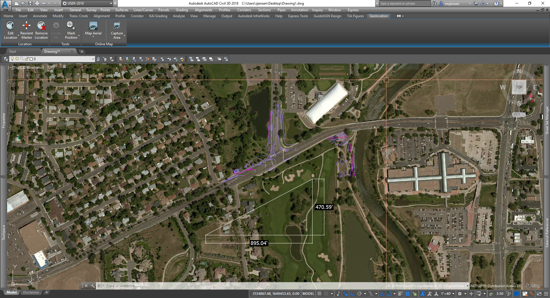
Finally, if you're wanting to bring in coverage areas from CAD to drape on the terrain (i.e. textures like asphalt, concrete, etc.), then they will come into IW in the wrong spot if you just use the state planes grid. Those transformation settings that we applied earlier are embedded in the IMX file, but they won't be embedded in SHP or SDF files if you go that route for the coverages. So what I've typically done is put an X and Y shift in the data source configuration for the coverages so they move over to match the surface. I've attached a screenshot from CAD with the approximate values that you'd need to use.
Zachri Jensen, PE |

Message 3 of 5
05-03-2019
04:49 AM
- Mark as New
- Bookmark
- Subscribe
- Mute
- Subscribe to RSS Feed
- Permalink
- Report
05-03-2019
04:49 AM
Thank you so much for your help with this. I regularly deal with these modified coordinates and these large truncations on almost all of my projects. I did your steps and that worked, so thank you.
Message 4 of 5
11-20-2019
09:35 AM
- Mark as New
- Bookmark
- Subscribe
- Mute
- Subscribe to RSS Feed
- Permalink
- Report
11-20-2019
09:35 AM
This is the first time I read a post about this process and i works great. Using your transformation settings, I can use this method anytime (which is often) I'm working in ground coordinates and using the Geolocation map. I use to shift the map using a convoluted way, but your method is far more proficient. Thank you.
Message 5 of 5
12-04-2019
07:28 AM
- Mark as New
- Bookmark
- Subscribe
- Mute
- Subscribe to RSS Feed
- Permalink
- Report
Reply
Topic Options
- Subscribe to RSS Feed
- Mark Topic as New
- Mark Topic as Read
- Float this Topic for Current User
- Bookmark
- Subscribe
- Printer Friendly Page
Forums Links
Can't find what you're looking for? Ask the community or share your knowledge.
Post to forums

