Textured pattern over flat face

Textured pattern over flat face

maghox.fr
Contributor Contributor
3,889 Views
8 Replies
Message 1 of 9

Textured pattern over flat face

maghox.fr
Contributor
Contributor

Hello,
I've got to a point where I'm comfortable creating simple designs of flat parts in Fusion360 (plywood, flat-pack furniture). But I'm struggling a lot with giving the flat faces some geometric texture. I want something simple, done mostly with V-bit passes. But I'm having a real hard time modelling that.
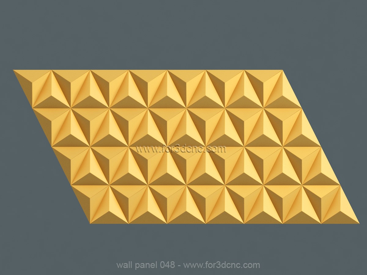
Ideally, I should be able to have several of these "textures" at hand and use them at will on different parts. I attached a picture similar to what I'm looking for.
1) From what I understand, that would be done by simply adding lines and using the 2D engrave toolpath. But, in order to make it work on an irregular, curvy part, should I design the grid on a vector software and import it to Fusion? I'm having a hard time creating the grid-lines only within the shape I want. (trimming seems to be the wrong approach to limit the lines to be contained within the desired shape).
2) If I wanted to model the V grooves, to see for myself before actually making the part, is there a simple way to do so? The only "quick" way I found was to run the simulation on the Manufacture enviroment and watch how it would look.
I don't ask often as I prefer to do my research and trial and error, but I'm really stuck on this one. Some pointing in the right direction where and what to look for would highly appreciated.
Thank you!

This is the part I designed.This is the part I designed.Textured part.Textured part.Example of texture I'd like to apply to the part.Example of texture I'd like to apply to the part.

0 Likes
Accepted solutions (1)
3,890 Views
8 Replies
Replies (8)
Message 2 of 9

daniel_lyall
Mentor
Mentor

For the texture, you want just sketch a line for each angle and pattern them in cam, not model cam.


Win10 pro | 16 GB ram | 4 GB graphics Quadro K2200 | Intel(R) 8Xeon(R) CPU E5-1620 v3 @ 3.50GHz 3.50 GHz

Daniel Lyall
The Big Boss
Mach3 User
My Websight, Daniels Wheelchair Customisations.
Facebook | Twitter | LinkedIn

0 Likes
Message 3 of 9

maghox.fr
Contributor
Contributor

I wasn't aware you could create patterns in CAM! I will read up and try it ASAP. Thank you!

0 Likes
Message 4 of 9

daniel_lyall
Mentor
Mentor
Accepted solution

You can do a sketch pattern if you want.


This is the outcome yjytjyjtyyyyyyyyyyyyyy.png


Example attached


Win10 pro | 16 GB ram | 4 GB graphics Quadro K2200 | Intel(R) 8Xeon(R) CPU E5-1620 v3 @ 3.50GHz 3.50 GHz

Daniel Lyall
The Big Boss
Mach3 User
My Websight, Daniels Wheelchair Customisations.
Facebook | Twitter | LinkedIn

0 Likes
Message 5 of 9

maghox.fr
Contributor
Contributor

Yes, that looks exactly like what I'm trying to do. I will try and probably ask you a couple questions if that's allright. Thank you for your time and help.

0 Likes
Message 6 of 9

daniel_lyall
Mentor
Mentor

Yes, that will be fine.


Win10 pro | 16 GB ram | 4 GB graphics Quadro K2200 | Intel(R) 8Xeon(R) CPU E5-1620 v3 @ 3.50GHz 3.50 GHz

Daniel Lyall
The Big Boss
Mach3 User
My Websight, Daniels Wheelchair Customisations.
Facebook | Twitter | LinkedIn

0 Likes
Message 7 of 9

maghox.fr
Contributor
Contributor

I tried it and was able to achieve what I wanted. For these simple textures it's exactly what I was looking for, thank you very much.
One question though: how would you limit the toolpaths to the part? As you can see, the part isn't a rectangle, so if I make the lines to be contained by the thicker part, they'll extend outwards on the thinner part. Is there a way to do it from the Manufacture enviroment?
Or is that only achievable by making a custom sketch for the part, instead of using the pattern as you suggested?
Again, thank you very much, wish you'd knew how helpful your answer was!

Texture.PNG

0 Likes
Message 8 of 9

daniel_lyall
Mentor
Mentor

This is one area where you have to be careful with the pattern you can use a sketch pattern for the toolpath and trim the lines to the edge of the part then use a 2D contour to do the toolpath as you can extend the toolpath enough so it leaves clean edges also in the passes tab you just set the compensation types to off for it to cut on the line.


The more sketch elements there are in fusion the higher the overhead on fusion is it can slow it down.


But there are ways around it like the areas where the lines are short you can use a sketch pattern there, then where they are the same length you can use a toolpath pattern.


Win10 pro | 16 GB ram | 4 GB graphics Quadro K2200 | Intel(R) 8Xeon(R) CPU E5-1620 v3 @ 3.50GHz 3.50 GHz

Daniel Lyall
The Big Boss
Mach3 User
My Websight, Daniels Wheelchair Customisations.
Facebook | Twitter | LinkedIn

0 Likes
Message 9 of 9

maghox.fr
Contributor
Contributor

OK I will take all of that into consideration. THank you very much!

0 Likes