Mirror CAM part

Mirror CAM part

JJackrabbit
Advocate Advocate
5,786 Views
15 Replies
Message 1 of 16

Mirror CAM part

JJackrabbit
Advocate
Advocate

Hi

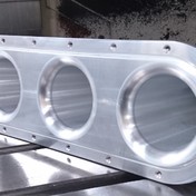
I've got a part  I need to make. It's a left and a right side. The only difference is that the part is mirrored. 

So I created a right hand side. Which I programmed. But what's the easiest way to mirror it, for the lh side? with all the toolpaths?

I prefer not to re-create all the toolpaths for a mirrored body.

Isn't it somehow possible to mirror the cam setup?


0 Likes
Accepted solutions (2)
5,787 Views
15 Replies
Replies (15)
Message 2 of 16

seth.madore
Community Manager
Community Manager
Accepted solution

2019-02-28_07h18_44.png


Duplicate your Setup, dump all your toolpaths into Pattern > Duplication and you are mostly good to go. The downside is that the toolpathss will be reversed (conventional instead of climb). Those will require manual intervention


Seth Madore
Customer Advocacy Manager - Manufacturing


0 Likes
Message 3 of 16

JJackrabbit
Advocate
Advocate

Thanks.

But I'm just going to create a mirrored body and re-program the part.

The mirror patern doesn't work that well imho.

Some toolpaths are off. And you don't see the actual mirrored body of course.

0 Likes
Message 4 of 16

seth.madore
Community Manager
Community Manager
Accepted solution

That is correct. You can mirror the body (around a given plane) in the Model space and then mirror the toolpaths in Pattern, using the same plane. Pretty much the only option at this point in time...


Seth Madore
Customer Advocacy Manager - Manufacturing


0 Likes
Message 5 of 16

BWENGUK
Advocate
Advocate
Is there any neater way of doing this 5 years later?

I too have a (fairly complex) part that has a right and left hand. I've modelled the left part and created the CAM setups for it. 6 separate setups for the part. Is there a way of mirroring the part in design so that all the references etc are kept? The current mirror within design just creates a new part, which would mean going through 30 ish operations and re-doing all the references.

Surely there is a better way? I've tried playing about with putting things in folders and setting them to mirror, but this gets very messy very quickly.
0 Likes
Message 6 of 16

programming2C78B
Mentor
Mentor

You cant do a Mirror pattern to the CAM? 

Please click "Accept Solution" if what I wrote solved your issue!
0 Likes
Message 7 of 16

dlewis1000
Advocate
Advocate

Even now there's no good way to do this. Holes are the only thing that work. Everything else flips cutting directions which makes it almost a pointless function. In defense to Autodesk, there's only a couple of systems out there that are capable of flipping cutting directions on a mirror. Been programming a long time and complex mirrored parts are some of my least favorite for this reason. 

0 Likes
Message 8 of 16

BWENGUK
Advocate
Advocate
Appreciate the reply. My 'simple' solution to this would be to allow mirroring within the design work space without having to create a new part. I think in Solidworks for example, you can 'scale' the part and put -1 in and it'll invert the part. This would then allow regeneration of toolpaths keeping all of the references correct.

If you could mirror a part and transfer all the references this would be 90% of the problem solved. That way all the edges, faces, heights etc etc that are selected within the the toolpaths will stay selected.

I guess this is more complex then it seems on the surface!
0 Likes
Message 9 of 16

seth.madore
Community Manager
Community Manager

@BWENGUK wrote:
Appreciate the reply. My 'simple' solution to this would be to allow mirroring within the design work space without having to create a new part. I think in Solidworks for example, you can 'scale' the part and put -1 in and it'll invert the part. This would then allow regeneration of toolpaths keeping all of the references correct.


I seem to recall the "Scale -1" being a solid workaround in Fusion as well, but having just tested this, it does not like the notion of a -1 🤔  (I wonder if we changed something)


Seth Madore
Customer Advocacy Manager - Manufacturing


0 Likes
Message 10 of 16

seth.madore
Community Manager
Community Manager

Yep, still possible, just need to use a Parameter to drive the scaling:

(view in My Videos)


Seth Madore
Customer Advocacy Manager - Manufacturing


Message 11 of 16

BWENGUK
Advocate
Advocate

@seth.madore this is exactly what I was looking for! I had tried scaling by -1 but that didn't work. I didn't think to use parameters to force the matter. This is perfect, thank you, insightful as always!

0 Likes
Message 12 of 16

dames123
Advocate
Advocate
"In defense to Autodesk, there's only a couple of systems out there that are capable of flipping cutting directions on a mirror."

Yes, and they own one of them. I hope they port this functionality over soon.
0 Likes
Message 13 of 16

gavin
Explorer
Explorer

Is there a way to do this in Inventor?

I tried this in Inventor using the "Direct" function from the modify tab, and then tried to use the scale solids function but it did not accept the unitless user parameter as the driver.


0 Likes
Message 14 of 16

programming2C78B
Mentor
Mentor

for anyone new, if you simply use a circular function (draw one on your mirror plane location) it will respect your cut directions! 

Please click "Accept Solution" if what I wrote solved your issue!
Message 15 of 16

david.lundbergC7AM5
Advocate
Advocate

Wow. That saved me a couple of hours.👌

0 Likes
Message 16 of 16

nassim_sparks
Contributor
Contributor

I don't understand how you would do this. When you use a circular pattern, it's not going to be a mirrored part? It would be the same part, just flipped 180 degrees, unless I am missing something.