


Simulation : Linear Global Load
- Mark as New
- Bookmark
- Subscribe
- Mute
- Subscribe to RSS Feed
- Permalink
- Report
Hello,
I've been learning and working with Fusion 360 for a couple of months on and off, and doing good progress on the design of a sort of CNC mill that I want to build. Now that I have the basic concepts and design decisions done, I would like to refine the definition of some critical parts, with the help of Simulation.
The machine is similar to a router, except that it has an extended Z arm, giving me about 1000 mm high work volume. The spindle and, if things go well, B/C head to which it is attached, will weigh about 15 kg. So, when the mill is lowered to its maximum depth, I have this mass dangling at the end of the 1000 mm free Z arm. For now, the Z arm is made of a square steel tube, 150x150x5 mm section.
I'm now trying to dimension the Z beam so that it doesn't flex too much when the mill is moved in the X/Y direction but still remains not too heavy. I've tried several ways to represent this case with Simulation, with results varying by an order of magnitude.
This is what I've done :
- Constraints : the z beam is attached to the rest of the machine through 4 linear motion blocks. I have set fixed constraints to the back and inner faces of these blocks
- Loads : I have activated the Gravity, and, in order to represent the effects of inertia, I have also :
- added a Manual point mass of 15 kg set to the lower end of the z beam, that represent the spindle and B/C head
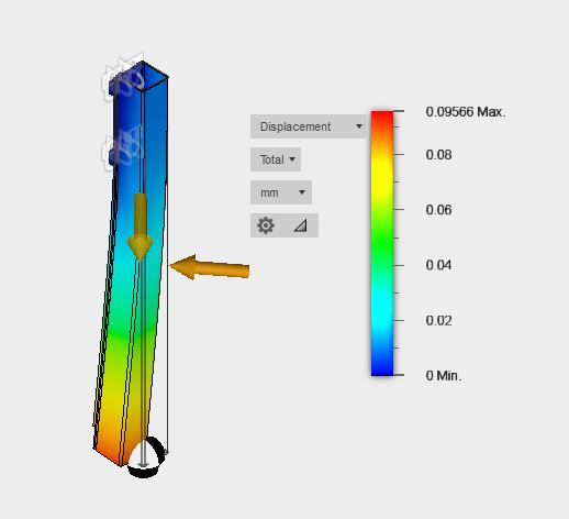
- applied a Linear Global Load to a corner edge of the beam, with a magnitude of 7 m.s-2 to represent a combined maximum acceleration of 5 m.s-2 in the X and Y directions
- Contacts : I've run the Automatic Contacts command and left the resulting contacts as is (an attempt to define the contacts between blocks and rails as Sliding resulted in a model that could not be solved)
This gives me a max. displacement of +/- 0.1 mm. (zBeam Simul 1.jpg)
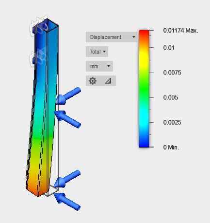
I have also tried to represent the inertia as forces applied to the beam and beam end, equivalent to mass x acceleration, in the X and Y directions. This gives me about 0.01 mm (zBeam Simul 2.jpg)
Please note that I have not represented the effects of the cutting forces that apply to the end of the mill tool : as the machine is meant to work on soft material, I assume that I can safely ignore these at this stage.
Questions :
- is any if these models relevant to what I'm trying to measure ?
- which one would be closer to what happens in reality ?
- what would be a better way to create a more accurate model ?
- what exactly is a "Linear Global Load" and how different is it from a Structural Load ?
Being very new to Fusion 360 Simulation and FEA in general, I appreciate any guidance, and thank you for your help