Refining chamfer on waving edges

Refining chamfer on waving edges

twan_peeters
Enthusiast Enthusiast
1,261 Views
12 Replies
Message 1 of 13

Refining chamfer on waving edges

twan_peeters
Enthusiast
Enthusiast

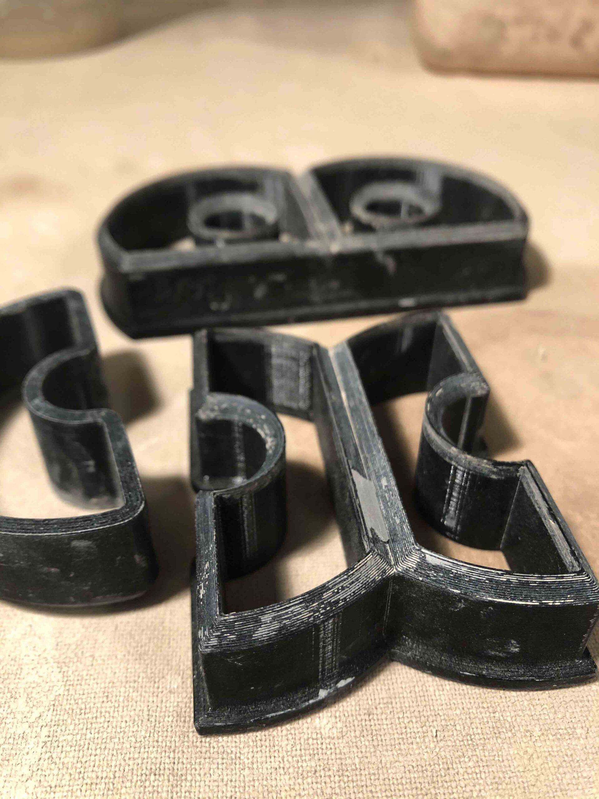
I am creating a cookie-cutters for clay that are used to make earrings. I've successfully made a lot of geometric shapes already and printed them in PET plastic (see example), but I've started running into chamfer problems with the more 'advanced' and wavy shapes.


In the video I show my process that describes the problem. I didn't get Screencast to work but I hope this helps: 


The outer offset line created some pointy corners that won't allow for chamfering, so I added a 1mm fillet to all of corners to make it more smooth. However, whenever I chamfer this, the chamfer only goes to 2.99mm, leaving parts of the shape flat and unchamfered. If I print it like this, it might give problems when trying to cut the clay shapes, as there are inconsistenties in the sharpness of the edge.


I understand that the fillets that I added to the sketch result in a slight inconsistency between the inner and outer line of the sketch, but is there a way to fix the problem and have a perfectly smooth and sharp corner through out the shape? This seams to be working fine with many other shapes, such as the printed example I attached.


Your help will be greatly appreciated.

0 Likes
Accepted solutions (1)
1,262 Views
12 Replies
Replies (12)
Message 2 of 13

jhackney1972
Consultant
Consultant

Due to the fillets, you added in the layout sketch, the wall thickness is not constant.  Therefore I had to make the chamfer leg hang over the inside edge slightly to make a complete cur around the full part.  Model is attached.


Chamfer.jpg

John Hackney, Retired
Did you find this post helpful? Feel free to Like this post.
Did your question get successfully answered? Then click on the ACCEPT SOLUTION button.

EESignature

0 Likes
Message 3 of 13

twan_peeters
Enthusiast
Enthusiast

Thank you John, this model now has much sharper edges. I have quite a few models that have a similar problem, would you be able to explain how you used the software to do this so I can apply this myself? 


@jhackney1972 wrote:

Due to the fillets, you added in the layout sketch, the wall thickness is not constant.  


I only put in the fillets because without them the shape would not chamfer at all, it will give me an error. Was it a good decision to put in the fillets to counter this? 


Have a wonderful day!

0 Likes
Message 4 of 13

jhackney1972
Consultant
Consultant

I am not implying that you do not need the outside fillets, I just feel you should use a different method of establishing your wall thickness to make it consistent.  I demonstrate one method in my Screencast at the beginning. I go on to show you how I created the beveled edge.  If you want to follow along using the timeline in my previously submitted model, that would help you understand the process.

John Hackney, Retired
Did you find this post helpful? Feel free to Like this post.
Did your question get successfully answered? Then click on the ACCEPT SOLUTION button.

EESignature

0 Likes
Message 5 of 13

TheCADWhisperer
Consultant
Consultant

Attached is a general solution.

Message 6 of 13

jhackney1972
Consultant
Consultant

Now that is a cool way to do create the edge!  I will have to remember that one.

John Hackney, Retired
Did you find this post helpful? Feel free to Like this post.
Did your question get successfully answered? Then click on the ACCEPT SOLUTION button.

EESignature

0 Likes
Message 7 of 13

TheCADWhisperer
Consultant
Consultant
Accepted solution

@jhackney1972 , @twan_peeters 

Here is simplified technique...

0 Likes
Message 8 of 13

twan_peeters
Enthusiast
Enthusiast

Thank you so much John, CADWhisperer. I have tried both techniques and I learned so much from going through the steps and watching your video. 


With both techniques although it makes the edge completely sharp there is one problem, it creates inconsistent height differences along the top path. I have added a video to show what I mean. 


https://autode.sk/3tuCgai


Based on what you taught me John I ended up just reverse offsetting the outer edge inwards and using that for extrusion instead. That method will clear out the inconsistencies. It does alter the shape of the cookie-cutter slightly but as the jewellery always had been handmade the difference is acceptable. 


Would there be in future events however a way to chamfer or cut this little section (especially the small top triangle) separately? So the idea would be that the small patch that is now flat also will be angular, so that the shape will remain intact, but the edge will have some sense of sharpness to it. The top will have to be completely flat with no height differences.


twan_peeters_0-1612544198713.png


Thank you for your time, I'm quite new to Fusion 360 and this is all extremely helpful!


0 Likes
Message 9 of 13

twan_peeters
Enthusiast
Enthusiast


0 Likes
Message 10 of 13

jhackney1972
Consultant
Consultant

As I mentioned in my video, your wall thickness was not consistent.  What I did in the attached model is to edit your first sketch, erase the inner loop and offset the outer loop 3mm inside to recreate it.  This will automatically give you a consistent wall thickness.


Offset Outside.jpg

Since it is now consistent, I could create the sweep profile exactly to the edges of the body and then when the sweep occurs, the final sharp edge is even across the face.


Sweep Sketch.jpg

Model is attached.

John Hackney, Retired
Did you find this post helpful? Feel free to Like this post.
Did your question get successfully answered? Then click on the ACCEPT SOLUTION button.

EESignature

0 Likes
Message 11 of 13

twan_peeters
Enthusiast
Enthusiast

Thank you John. I think there might have been a misunderstanding - I do understand the solution of offsetting back in from the outer wall to get a consistent wall thickness. This is also what I have done now to the model. However this results in the model not following the exact shape anymore that I was tracing initally.


Even though offsetting from the inner shape will create an inconsistent wall and therefore not a perfectly sharp path, In my question I meant weather it was possible at all to polish a few the remaining flat surfaces after using this method. 


It could be more important to me in the future to stay true to the original shape and offset from the inner line rather than the outer line and changing the inner shape.


Thank you so much for your time and help.


0 Likes
Message 12 of 13

jhackney1972
Consultant
Consultant

The answer to your question posed in the screen capture is NO, I do not have a way to smooth out the sections indicated.  I used basically the method the @TheCADWhisperer showed you with a couple of changes.  One, I did use an offset to maintain wall thickness but I used the inside wall as my base shape maintaining your original tracing.  Two, due to the fact that the final cutting edge kept getting out of perfect flatness, I added a step to trim off the top surface patch to make it perfectly flat.  I used his method but I probably did not execute it exactly as he would have but you get the final result.  Model is attached.


If and when you do Accept Solution for this post, make sure you accept his post since I am only executing his idea and example of how it should be done.


John Hackney, Retired
Did you find this post helpful? Feel free to Like this post.
Did your question get successfully answered? Then click on the ACCEPT SOLUTION button.

EESignature

0 Likes
Message 13 of 13

twan_peeters
Enthusiast
Enthusiast

Thank you so much John for your clear suggestions. I have successfully followed all the steps from you and CADwhisperer and I'm very happy it now stays true to the sketch! I learned so much!


Hope you have a wonderful day. Thanks!

0 Likes