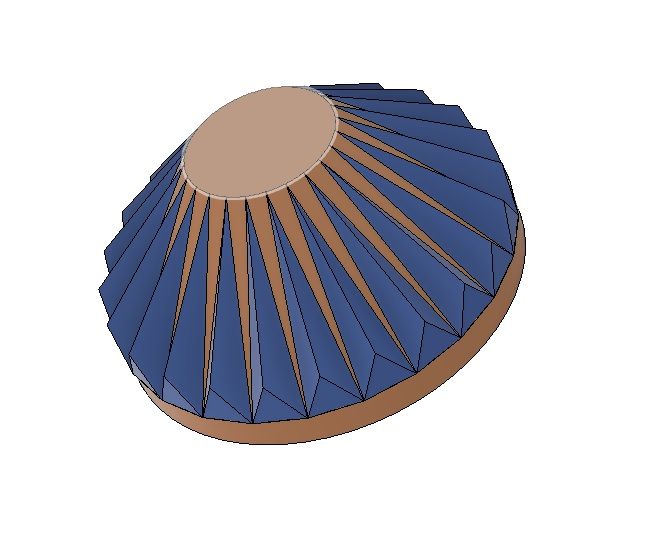
How do I create a bevel gear like this in fusion?

How do I create a bevel gear like this in fusion?

Anonymous
Not applicable
7,139 Views
13 Replies
Message 1 of 14

How do I create a bevel gear like this in fusion?

Anonymous
Not applicable

Hi, I am a complete beginner in CAD and Fusion, As a project I am trying model to an Align trex 450 Pro RC helicopter but I have come to this part and cant figure out how to model it properly. My modelled part has flat faces on the top which don't match the profile of the actual part and if I delete them I get a star shape instead of a disc at the top of the cone and the angle of the profile is then wrong. Is it possible to create a part like this in fusion and if so how?
 

Bevel.PNGIMG_0078.JPG

0 Likes
7,140 Views
13 Replies
Replies (13)
Message 2 of 14

nvanlaar
Advocate
Advocate

I created a quick screencast of how I would do it.  Let me know if it helps.


I can't get the screencast thingy to work...


Bevel gear Screencast


Message 3 of 14

TrippyLighting
Consultant
Consultant

Generally not a bad approach, however, the teeth are wider at the bottom than at the top.

 In order to get het right geometry you'll need to divide the top and bottom circe into equal segments and then extrude a shape from that.


EESignature

0 Likes
Message 4 of 14

etfrench
Mentor
Mentor

The hard way to do this would be:

  1. Create a sketch of the top view of the gear
  2. Draw a circle the diameter of the gear
  3. Draw a line from the center of the circle to the circumference.
  4. Make a Circular Pattern of the line with double the tooth count of the gear
  5. Create a sketch for the side view of the gear tangent to the circumference.
  6. Project three of the end points of lines from the circular pattern to this sketch
  7. Draw a line from the middle projected point with a height of a gear tooth at the perimeter.
  8. Draw a triangle using the points
  9. Do a loft between the triangle and the point where the tooth meets the top of the gear. (You may need another sketch to locate that point)
  10. Use a Circular Pattern to create the teeth
  11. Use a Revolve operation to create the body of the gear

BevelGear.jpg

The easy way would be to install the Bevel Gear app from the app store Smiley Very Happy


ETFrench

EESignature

0 Likes
Message 5 of 14

etfrench
Mentor
Mentor

@TrippyLighting wrote:

Generally not a bad approach, however, the teeth are wider at the bottom than at the top.

 In order to get het right geometry you'll need to divide the top and bottom circe into equal segments and then extrude a shape from that.


And you'll also need to fillet the top and bottom of the teeth.  If the gear is involute then you'll need to modify the sides as well.

ETFrench

EESignature

Message 6 of 14

nvanlaar
Advocate
Advocate

Another way I did it was:

1) Create base shape (green)

2) project to another sketch plane 

~both of these steps require a small extrusion.~

3) scale the upper (small) extrusion to the appropriate size (yellow)

4) loft from the large gear to the small gear.

Additional fillets/chamfers can be done.  Also, push pull can be used to adjust height.


bevel gear.png 


0 Likes
Message 7 of 14

daniel_lyall
Mentor
Mentor

A even easier way to do it use the bevel gear plugin.


https://apps.autodesk.com/FUSION/en/Detail/Index?id=2791960362914790676&appLang=en&os=Win64


Win10 pro | 16 GB ram | 4 GB graphics Quadro K2200 | Intel(R) 8Xeon(R) CPU E5-1620 v3 @ 3.50GHz 3.50 GHz

Daniel Lyall
The Big Boss
Mach3 User
My Websight, Daniels Wheelchair Customisations.
Facebook | Twitter | LinkedIn

0 Likes
Message 8 of 14

etfrench
Mentor
Mentor

That's two votes for the Bevel Gear app Smiley Surprised


You will need to create a new center body that has a top diameter the same as the upper tooth max diameter and a lower diameter of the lower tooth min diameter in order for it to match the helicopter gear. Use the Combine|Join operation to create the final gear model.

ETFrench

EESignature

0 Likes
Message 9 of 14

HughesTooling
Consultant
Consultant

Has anyone tried the bevel gear plugin and are the gears correct. Looking at the screen shots it looks like all it does is create 2 flat involute gear profiles and lofts between them.


Like in this picture where I've used Fusion's gear plugin to make 2 gears then loft between them.

before.png

This will not give the correct tooth form. To do it correctly you have to rotate the tooth form to match the angle of the bevel like this.

Clipboard01.png

Two gears made with the plugin will probably run OK but I don't think it will work too well if you tried using a gear made with the plugin with a gear manufactured correctly.


Mark Hughes
Owner, Hughes Tooling
Did you find this post helpful? Feel free to Like this post.
Did your question get successfully answered? Then click on the ACCEPT SOLUTION button.

EESignature


0 Likes
Message 10 of 14

Anonymous
Not applicable

Hi, Could you post a screencast of this process, it looks like the closest to the part. I got up to step 5 but I'm a bit confused, How do I make the plane tangent to the sketch circle, it asking for some geometry. Do I need to build any geometry in the first 4 steps?

0 Likes
Message 11 of 14

TheCADWhisperer
Consultant
Consultant

Can you post more screen shots of the original gear?

Perhaps hit it with a shot of dark spray paint first.


It is hard to tell from the picture, but is the crest tapered or same width from end to end?

It is hard to tell from the picture, but is the root tapered or same width from end to end?

Do the sides appear to be simple "planar" faces or do they appear to be arc faces?


Do you have calipers? Can you give a few measured dimensions?

0 Likes
Message 12 of 14

Anonymous
Not applicable

Hi, The gear dia is 13,75 mm across the widest point, The cone at the top is around 4.5mm, the length of tooth face is around 5.5mm, Its hard to get really accurate as its plastic and quite small. With the naked eye it looks like the teeth taper flush with the cone at the top, but a closer look at the photos suggest that the tooth ends sit just proud of the top edge of the cone. Ive posted a couple more pic and highlighted the teeth with marker pen to give some constrast.


IMG_0080.JPGIMG_0081.JPGIMG_0081.JPG

0 Likes
Message 13 of 14

Anonymous
Not applicable

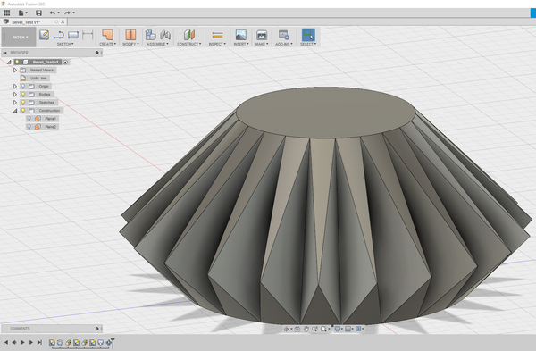
Ok after having some thoughts after the replies to this post, I changed the profile shape and position and did a lofted join instead of a lofted cut, and now its much closer to what the part actually looks like, Of course I have to get it dimensioned correctly but this is what I have now


Bevel_Test.PNG

0 Likes
Message 14 of 14

etfrench
Mentor
Mentor

This screencast shows one way of creating the teeth.  They are still not the correct shape.  You'll need to use an involute form instead of a triangle.  In addition, the valleys between the teeth need to be a constant distance from top to bottom. Your gear is probably a module 0.5 if metric or Diametrical Pitch 48 if Imperial.

ETFrench

EESignature

0 Likes