Geodesic Dome 2V/3V

Geodesic Dome 2V/3V

stud.magraf
Enthusiast Enthusiast
38,457 Views
27 Replies
Message 1 of 28

Geodesic Dome 2V/3V

stud.magraf
Enthusiast
Enthusiast

Hi All,


attention: long post! 😛


First of all I want to take the opportunity to reach out to @lars_christensen . I want to thank you for all the good resources you put out there, they're a great help!


To me: I am an electrical engineer from Germany with multiple interests and I always wanted to make things. Now my mind is not made to just make things, I need a tool that allows me to make what I want virtually and spit out plans with which I can make the actual thing. That's where Fusion comes in handy.


I spent the last couple of weeks in hospital and I took the chance to watch tons of videos, primarily of Lars, and started to get little things to work. I already made my own box with hinges and o-ring and stuff.


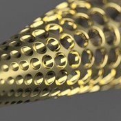
Now I have found something inspiring in the web and I want to put this into a param


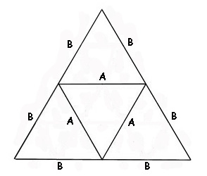
Now if I am not too wrong this should be a Geodesic Dome 2V. The best resource for those I could find is this one: https://www.ziptiedomes.com/geodesic-dome-calculators/2v-geodesic-dome-calculator.htm . What this gives me is the dimensions of the triangles I need.


Here's what I would do:

1. Create a polygon with 12 corners on level 0 with the wanted diameter. Place it so that two corners are horizontal.

2. Create an offset plane at the height of the triangles 'A' and place another polygon on it with 12 corners.

3. Create an third offset plane above the second by the height of triangle 'B' and place a hexagon on it.


Questions:

1. Is the distance between ground level and level 1 correct?

2. Is the diameter of the second polygon correct?

3. What diameter and distance does the hexagon have?

4. How do I sketch the triangles? I have to connect the corners of the two polygons I made. Do I have to create another sketch in the origin XY plane and project the two polygons?

5. I don't want to use connectors, I want to screw each triangle to its neighbor. This will create several angles on the ends of each strut. I want to let Fusion create those angles while placing the struts. But how do I create the struts on the triangle sketches (do another sketch and project?) and how do I take care that the angles are cut?


I know I know. A long post from a newbie with a lot of questions ... I get to the point where I have placed the two polygons but because of my questions not farther. I will place screenshots as I try to follow along your answers (hopefully 🙂 ).


Thanks from Germany!
0 Likes
38,458 Views
27 Replies
Replies (27)
Message 2 of 28

jasonhomrighaus
Collaborator
Collaborator

Well that was a fun little challenge!


I figured out a way to do it but it doesn't match up to what you were describing.


Hopefully this will give you some ideas on how to proceed.  Its tougher than it looks.


Let me know if I can help you out in any way


You can change the dome size by changing the dimension d1 in the first drawing.


I didn't try changing the Slat dimensions i lost enough hours figuring this much out.

Man LOL

Paramatized Geodesic v3.png

Message 3 of 28

TrippyLighting
Consultant
Consultant

Very nice!


EESignature

0 Likes
Message 4 of 28

stud.magraf
Enthusiast
Enthusiast

Hey


sorry it took me a few days to check this out. Thank you very much! I didn't mean to make other people work, that was not my intention.


I can see a whole lot of paramteres where I would have expected one: the outer diameter. Can you explain more about how this was made?


Thanks in advance.


edit: How to change the diameter in your version?

0 Likes
Message 5 of 28

TrippyLighting
Consultant
Consultant

You can open the attached file and go through the timeline.

Also, if you increase the size you'll see lack of precision accumulating due to the use of a fixed precision angle, instead of a formula.


EESignature

0 Likes
Message 6 of 28

stud.magraf
Enthusiast
Enthusiast

I have seen from the timeline that the whole thing is built more or less strut by strut. I am trying to get something by using this https://www.ziptiedomes.com/faq/What-Is-Geodesic-Dome-Frequency-Explained.htm source.

0 Likes
Message 7 of 28

jasonhomrighaus
Collaborator
Collaborator

First you do not need to be concerned about the work it was a challenge and time well spent. 


I agree that some sort of formula would help but I didn’t not find one readily available to use in the design. 


The angles are more complex than they seem. It’s not as simple as a direct division of the circle as they are all compounded. 


As to the construction it is not strut by strut but rather triangular element by element for the equalateral triangles and pentagram by pentagram for the isosolese triangles. 


You can change the diameter of the structure by changing the dimension in the first sketch(just double click on it and change the value)

0 Likes
Message 8 of 28

stud.magraf
Enthusiast
Enthusiast

Well I spent some of my spare time I have here in the hospital to do some research. What I got so far:


Problem: define a geodedic dome with a frequency of 2 only by its diameter.

Equations:

Diameter: d

Radius: r

Height: h=0.5*d

Strut length: lstr_A=d/2*0.61803 lstr_B=d/2*0.54653


Missing link: Diameter and distance from level 1 > level 2 and level 2 > level 3


Now my idea would be to construct struts A and B, create the two 12 edge polygons and the hexagon and build the Icosahedron with the struts and rotate that around. By doing so it should give a fully paramaterized dome...


0 Likes
Message 9 of 28

TrippyLighting
Consultant
Consultant

I fully understand 😉 I had just finished this tutorial on a regular and truncated Icosahedron before this thread came along.


The V2 (model attached) and V3 Geodaesic domes are just natural extensions of the Icosahedron. One just has to divide the edges of the Icosahedron by 2, or 3 and project those out to the circumscribing sphere. the attached file isn't quite in a finished state as far as geometry goes, but the base framework is there.


EESignature

Message 10 of 28

TrippyLighting
Consultant
Consultant

@stud.magraf the difficulty is not so much calculating the strut lengths, there are a number of online calculators available and other sources that also provide formulae.


As it pertains to Fusion 360 or other CAD systems (I've tried this more than 10 years ago in Solid Works) if you design the struts and use joints in Fusion 360 (or geometric mates in other CAD systems sch as SW ) to assemble this strut, by strut it is very easy to create an over constrained assembly.

With an Icosahedron that is still somewhat easy to manage, but with a V2 or V3 dome built from struts and connectors you're going to have a huge challenge on your hands.


EESignature

0 Likes
Message 11 of 28

stud.magraf
Enthusiast
Enthusiast

I actually would have thought that its easier to just build it in fusion rather than computing it... thing is that each of those struts has to be a component so that I can create drawings of them.


Huh and I thought I make it easier by using Fusion, build it there and to the software do all the magic stuff to give me the angles I need to cut 😄 but it seems like I should just use this russian page I found and hope for the best?


There are great solutions in this thread! I will continue playing along with the first one, maybe I get it modified for my needs. I already transfered the strut bodies to components (easy) so that I should be able to make drawings of them..

0 Likes
Message 12 of 28

TrippyLighting
Consultant
Consultant

As @jasonhomrighaus and my posts with attached files have already proven this can be build entirely in Fusion360.

It simply takes a little bit of inventiveness and knowing the tool set in Fusion 360.

You'll have to put in a bit of your own work to figure out things.


EESignature

0 Likes
Message 13 of 28

jasonhomrighaus
Collaborator
Collaborator
The photo that was attached was of a decahedron. So I built based on a decahedron.

Part of the problem with the proposed approach lies with the fact that the “levels” are not fixed and the points on those levels are different depending on which set of triangles you are looking at. It certainly looks that way in the picture but when you look closer there are not any other parallel plains with the same shape. There is a parallel pentagon at the top, I might see if I can define the sides based on that pentagon.

Put another way, the only place in the figure where all the junctions meet on a flat plain is at the widest part of the dome. And it is not equally sectionable on any other angle(at least not for the 2V
0 Likes
Message 14 of 28

Anonymous
Not applicable

Hi,

I only need the geodesic form, as in the design. not the solid parts. I am fine with a surface model of triangles that I can patch to a solid afterwards. This one does not scale well. tried to change the diameter value in sketch 1 to ca 130 mm bit that did not end well....

/Lars

0 Likes
Message 15 of 28

TrippyLighting
Consultant
Consultant

Would the attached  work ?


Screen Shot 2019-02-04 at 8.30.38 AM.png


EESignature

Message 16 of 28

MichaelT_123
Advisor
Advisor

Hi Mr. Lazzerazer,


You might find these resources useful.

Platonic Solids


Regards

MichaelT


MichaelT
0 Likes
Message 17 of 28

jasonhomrighaus
Collaborator
Collaborator

I tell you this is a nasty little bit of modeling to take it beyond just the dimensions and try to out put useable frame parts.


The geometry is a real bugger and i keep running into some tiny discrepancies in the face angle at the joints, like on the order of .0005 degrees but it is enough to create gaps at the corners.  I may be being overly OCD with it but i can get all the struts fitting great but only if they are rotated into position if i mirror or flip them then a get a little gap.


Would be curious what you guys find if you poke at it.


The parameters Allow you to adjust the width of the face frames(Widthofbar), the depth of the framework(domethickness) and the radius of the dome.


Dome V2 v3.pngIMG_1656.jpg

0 Likes
Message 18 of 28

jasonhomrighaus
Collaborator
Collaborator

Just a note on this, the Figure is 10 sided not 12


0 Likes
Message 19 of 28

jasonhomrighaus
Collaborator
Collaborator

See my post above this.  Might be useful for you.

0 Likes
Message 20 of 28

Anonymous
Not applicable
yes that looks fine!
i cant seem to see a download link but a360 is behaving weird right now. no
css formatting t all just plain vanilla html.

will check back later.
thanx

Lars
0 Likes