Enabling view of a 3D sketch in Drawing Tool

Enabling view of a 3D sketch in Drawing Tool

hmortim
Contributor Contributor
1,247 Views
5 Replies
Message 1 of 6

Enabling view of a 3D sketch in Drawing Tool

hmortim
Contributor
Contributor

Hi there,

I have been designing 2D / single plane tube parts using the Pipe tool and making drawings for those parts without issue (think "U" shaped tubes - like an over the head roll cage tube with two 90° bends). I can easily enable the parts' sketch view in Drawing to be able to measure the side lengths of the tube to calculate the total length of tube stock needed and where to put my start-of-bend markers (minus the centerline arc length -I have to hand calculate that myself. Fusion will only measure centerline radius and degree of angle.)


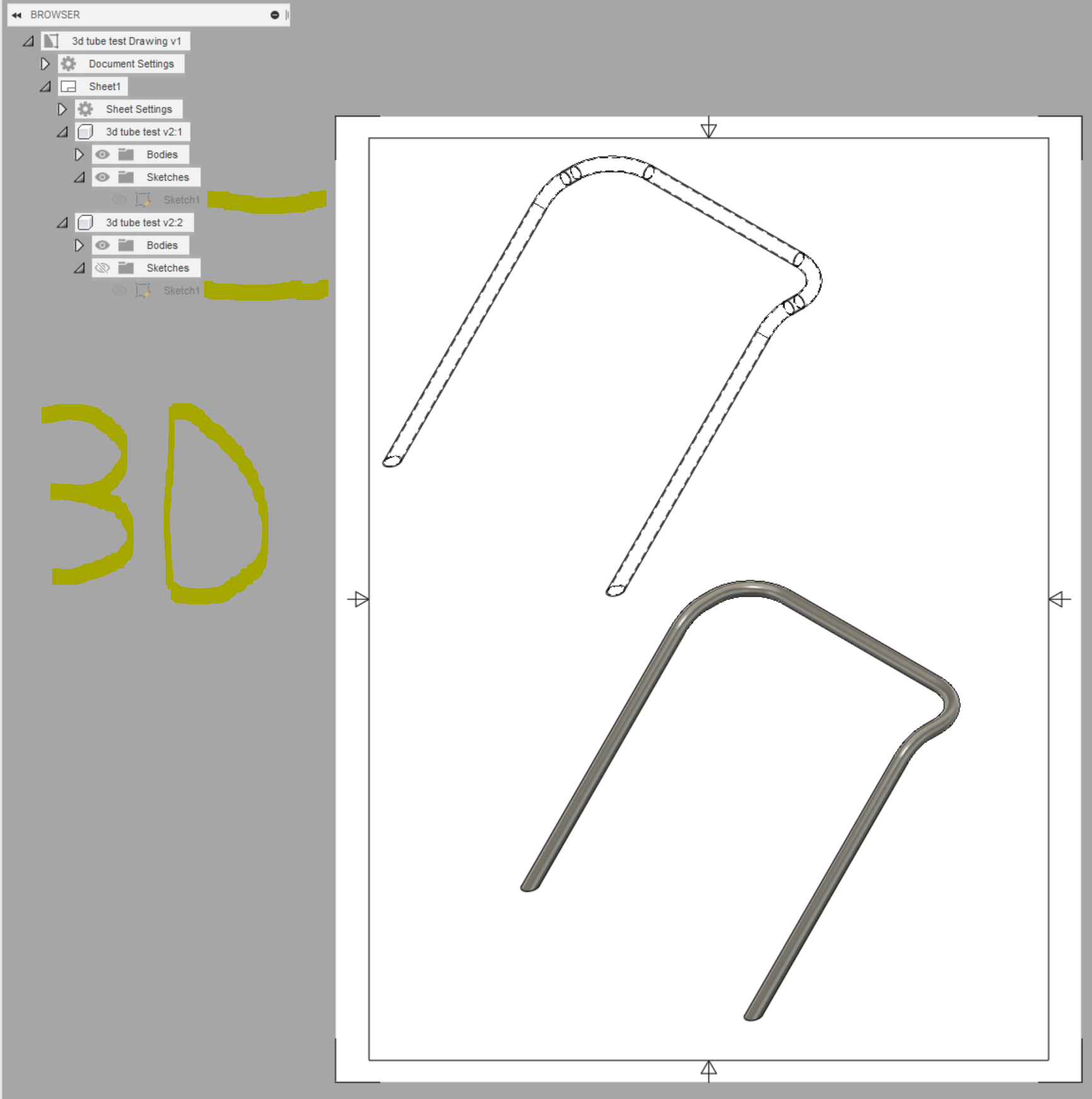
I am now designing bent 3d / multi-plane tubes. As I begin a Drawing document for them and place a standard side view, I notice the individual sketches are grayed out. I am unable to activate them to be able to calculate the total length of tube stock needed and where to put my start-of-bend markers. 


How can I make this work? Thanks in advance

0 Likes
1,248 Views
5 Replies
Replies (5)
Message 2 of 6

HughesTooling
Consultant
Consultant

As you've found 3d sketches are blocked in the drawing workspace. All you can do is create sketches for the views you are going to use and project the 3d sketch curves to a plane in the design workspace. 

Mark Hughes
Owner, Hughes Tooling
Did you find this post helpful? Feel free to Like this post.
Did your question get successfully answered? Then click on the ACCEPT SOLUTION button.

EESignature


0 Likes
Message 3 of 6

ClintBrown3D
Autodesk
Autodesk

Hi @hmortim 


As @HughesTooling suggests, you can project the lines to a sketch and make it visible on the drawing. I've made you a video to show how to achieve this here:


Clint Brown
Senior Product Manager - Autodesk Fusion


Book some time on my calendar
The Ultimate Guide to Drawing Automation
Message 4 of 6

TheCADWhisperer
Consultant
Consultant

@hmortim wrote:

 -I have to hand calculate that myself. Fusion will only measure centerline radius and degree of angle.)


Are you including bend allowance in the calculation for stretching of the tube at bends?

Can you File>Export your *.f3d file to your local drive and then Attach it here to a Reply?

0 Likes
Message 5 of 6

hmortim
Contributor
Contributor
I know that my 5.5" Center Line Radius die will produce an actual 5.9" CLR, through measurements and trial and error parts. So now I 2D design everything with 5.9" CLR and everything comes out to within ± 1/8" over 6 feet no problem.
0 Likes
Message 6 of 6

hmortim
Contributor
Contributor
Thank you for that demonstration. It's helpful for sure, just not sure how accurate it will really be to the design or actual bent product.

There's another CAD software called Bend-Tech that is optimized for tube work. I would love to see the Fusion team make a Tube / Pipe module like they did for sheet metal.

Features like: Spring Back Calculator, Centerline Adjustment, Bending Simulation, Die Library, Bend Calculation Output (length of tube to cut, bend 1, 2, 3 positions from end of tube with degree of orientation), Bend Order Manipulation, Printable Cutting Wrappers, etc.

I have submitted my requests in the survey they sent me, but who knows when / if they'll get to it.
0 Likes